Table of Contents
Advertisement
Quick Links
No.26600-2-01-10
User's Manual
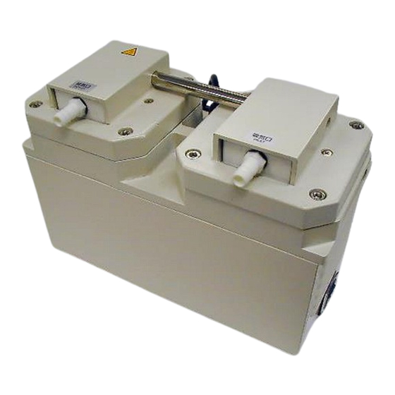
Diaphragm-type Dry Vacuum Pump
Model: DTC-60
Request to Users
Please read this manual thoroughly to ensure safe and
effective use of the equipment.
Keep this manual in a safe place.
Due to periodic improvements in performance, the
equipment described in this manual is subject to
changes in dimensions and specifications without prior
notice.
ULVAC KIKO,Inc.
Advertisement
Table of Contents

Related Manuals for Ulvac DTC-60


Summary of Contents for Ulvac DTC-60
- Page 1 No.26600-2-01-10 User’s Manual Diaphragm-type Dry Vacuum Pump Model: DTC-60 Request to Users Please read this manual thoroughly to ensure safe and effective use of the equipment. Keep this manual in a safe place. Due to periodic improvements in performance, the...
-
Page 2: Table Of Contents
Contents Pages with a shaded background are those which contain items related to safety. Before Using the Equipment ....................01 Checks When Opening Packaging ..................02 Using the Pump Safely ......................03 • Safety icons ........................03 • Cautions for Safety in Use ....................04 1. - Page 3 Figures and Tables Fig.2.1 DTC-60 Dimensions ....................2 Fig.3.1 Example of Piping Used When Evacuating a Vessel ..........4 Table 1.1 Product Specifications .................... 1 Table 6.1 Consumables List ....................6 Table 6.2 Locations for Maintenance and Inspection ............. 7...
-
Page 4: Before Using The Equipment
Before Using the Equipment Thank you for purchasing this product. Your custom is very much appreciated. This pump is designed solely for vacuum discharge, and may malfunction or cause accidents if not handled appropriately. Read the manual thoroughly, and pay due attention to inspections, maintenance, and safety. -
Page 5: Checks When Opening Packaging
Checks When Opening Packaging Check the following after opening the packaging. (1) Is the product as you requested? (2) Are the accessories and necessary parts included? Standard accessories ・User’s manual -------------------- x 1 ・Inlet and outlet caps (fitted to inlet and outlet) -------------------- x 2 ・Power plug adapter (attached to power cord) -------------------- x 1... -
Page 6: Safety Icons
Using the Pump Safely To ensure that the pump is handled correctly, read this section thoroughly before use. This manual and the warning labels on the pump include safety icons as an aid to understanding safety requirements. These safety icons warn the operator and others of possible dangers and damage and should always be followed. - Page 7 Cautions for Safety in Use Danger Applications (1) This pump is not designed to be explosion-proof, and should therefore not be used to discharge explosive gases. (2) In addition to discharge of gas via the outlet, gas may also leak from other parts of the pump, and it should therefore not be used with toxic gases.
- Page 8 Warning Operation (14) This pump is not designed to be explosion-proof. When using the pump, ensure that there are no inflammable materials such as solvents, or explosive gases, in the vicinity. Use under such conditions may result in injury or fire. (15) Inserting fingers or objects into the motor inlet may result in electric shock, injury, or fire.
- Page 9 Caution Maintenance and Repair Dispose in accordance with legislation for disposal and cleaning of waste products, handle as industrial waste, and do not incinerate. Toxic fluorine gas is generated by incineration of fluorine-based plastics. (10) If the pump ceases operation, turn power OFF (set switch to O) immediately to prevent accidents, remove the power cord from the wall outlet, and contact your dealer or the manufacturer for inspection and repair.
- Page 10 Note Operation Use the pump within an ambient temperature range of 40°C. Use at high ambient temperatures will dramatically reduce the life of the pump. Back pressure at the outlet while the pump is starting may overload the motor. (10) The thermal protection relay operates when the pump reaches a very high temperature. Touching the pump in this condition may result in burns.
-
Page 11: Product Outline
(4) Ensure that the gas entering the pump does not contain rubbish, dust, or water (except steam). (5) Do not operate the pump for long periods at near-atmospheric pressure. 1.2 Specifications Table 1.1 Product Specifications Model DTC-60 Discharge rate 50Hz (L/min) 60Hz Pressure achieved(Pa) 1.0×10... -
Page 12: Thermal Protection Relay
2) It is recommended that additional protective devices (eg. earth leakage breaker, motor breaker) be fitted. Warning See Warning (8), P04 See Caution (6), P05 Caution 2. Dimensions O.Dφ14 I.Dφ9 Fig.2.1 DTC-60 Dimensions... -
Page 13: Using The Pump Safely
3. Installation and Storage 3.1 Cautions for Installation and Storage See Warning Warning (1)(2)(3)(5)(6)(7)(8)(9)(10)(11)(12)(13), P04 Caution See Caution (1)(2)(3), P05 Note See Note (1)(2), P06 3.2 Environmental Conditions for Installation, Storage, and Operation The fine clearances used in this pump require that the following conditions be satisfied during storage, installation, and operation. -
Page 14: Cautions For Safety In Use
5) When starting the pump, it may not start if the intake-side pressure is lower than the atmospheric pressure. Attach an atmospheric release leak valve between the pump intake pipe and vessel, and set the intake-side pressure to atmospheric pressure when starting the pump. After starting the pump, always close the leak valve. -
Page 15: Precautions When Starting
4.3 Precautions when starting 1) Starting in cold weather Cold weather will increase the viscosity of bearing grease and harden diaphragms, resulting in the pump being difficult to start. Follow the procedure below in such conditions. A) Turn the switch ON/OFF 2~3 times with the inlet open to atmosphere until the pump starts. If the pump still does not start, raise the ambient temperature to beyond 0°C. -
Page 16: Maintenance, Inspection, And Repair
6. Maintenance, Inspection, and Repair 6.1. Cautions for Maintenance, Inspection, and Repair Danger See Danger (3), P04 Warning See Warning (4)(17)(18), P04,05 Caution See Caution (9)(10)(11), P06 Note See Note (12), P07 Maintenance and repair by the customer’s repair technician is limited to the following procedures. Do not undertake other repairs, or make modifications other than the standard options supplied by the manufacturer. -
Page 17: Replacing And Cleaning Consumables
<Replacement Guide> Replace or clean components if performance is reduced or the following symptoms become apparent. Diaphragms : Replace if PTFE components are worn or peeling, or if rubber components are deformed, hard or cracked. Inlet and outlet valves : Replace if deformed, hard, or cracked. O-rings : Replace if hard, cracked, or stretched. -
Page 18: Replacement Of Diaphragms
1) Replacement of diaphragm (It is recommended that two diaphragms be replaced at the same time.) Caution Always wear gloves to reduce the risk of injury when mounting or dismounting the diaphragm. Hexagon socket Protection pipe Tools used: 2-②, 3-②, 5, 6, 7, 8 head cap screws (M6×25) (1) Remove the four hexagon socket head cap screws... -
Page 19: Replacement Of Inlet And Outlet Valves
(10) Apply a small amount of vacuum grease to an area of Protection pipe about 5 mm from both ends of the connection tube and insert the tube as deeply as possible into the hole on Casing the side of the pump head assembly . (Photo 5) After inserting the tube, mount the protection pipe and connect the two pump head assemblies. - Page 20 (6) Mount new inlet and outlet valves with the procedures of steps ① through ⑭ as shown below. ① Check the first stage side (inlet side) and second stage side (outlet side) of the pump referring to photo 9. ② Check the type and configuration of the inlet and outlet valves referring to Photo 10. (※...
- Page 21 ⑨ Prepare the second stage side pump head, inlet valve B (1), outlet valve A (1), and outlet valves (2) Inlet valve B ※ Hole opening referring to Photo 15. ④ ⑩ Face the marke (felt pen) side of inlet valve B Downwards and place it with the hole opening at the right side according to the arrow ④...
-
Page 22: Replacement Of O-Rings
3) Replacement of O-ring (It is recommended that the O-ring be replaced together with the diaphragm.) Tools used: 1, 2-①, 2-②, 3-①, 3-②, 4, 5, 6, 7 O-ring (N-11) (2) O-ring (P-38) O-ring (P-14) Photo 20 Photo 21 Photo 22 (1) Remove the inlet and outlet valves, the pump head, and the valve retainer with the procedures of steps (1) through (4) of Section 2 “Replacement of inlet and outlet valves.”... -
Page 23: Troubleshooting List
6.5 Troubleshooting List Table 6.3 Troubleshooting List Problem Causes Solutions Reference (1) Not connected to power supply. (1) Connect power supply. (2) Switch is OFF. (2) Set switch to I. (3) Ensure that voltage variation is within (3) Problem with power supply voltage. +/-10%. -
Page 24: In Conclusion
7. In Conclusion Please contact the manufacturer’s sales division if you have any questions. Warranty (1) The warranty for this pump (this equipment) extends for a period of one year from the date of shipment. (2) Any malfunctions or defects which occur under normal usage conditions during the warranty period will be repaired free of charge. -
Page 25: Usage Status Check Sheet
Usage Status Check Sheet (for use in Instruction Manual) * For the purpose of safety control of repair personnel, fill in within the heavy line frame and attach the sheet to the item of which repair is requested. * In case this sheet were not attached or filled in, your request of repair and service may not be accepted. - Page 26 No.62400-2-02-10 アルバック機工株式会社 https://ulvac-kiko.com 製品情報・サービス拠点・お問い合わせはこちらから https://showcase.ulvac.co.jp/ja/ 株式会社アルバック コンポーネント事業本部 営業部 〒253-8543 神奈川県茅ヶ崎市萩園2500 TEL:0467-89-2416 ULVAC KIKO,Inc. https://ulvac-kiko.com/en Please contact us for products, Service Base or other Inquiries from here. https://showcase.ulvac.co.jp/en/ ULVAC,Inc. Components Business HQ 2500 Hagisono, Chigasaki, Kanagawa, 253-8543, Japan TEL:+81-467-89-2261...
Need help?
Do you have a question about the DTC-60 and is the answer not in the manual?
Questions and answers