Advertisement
Available languages
Available languages
Quick Links
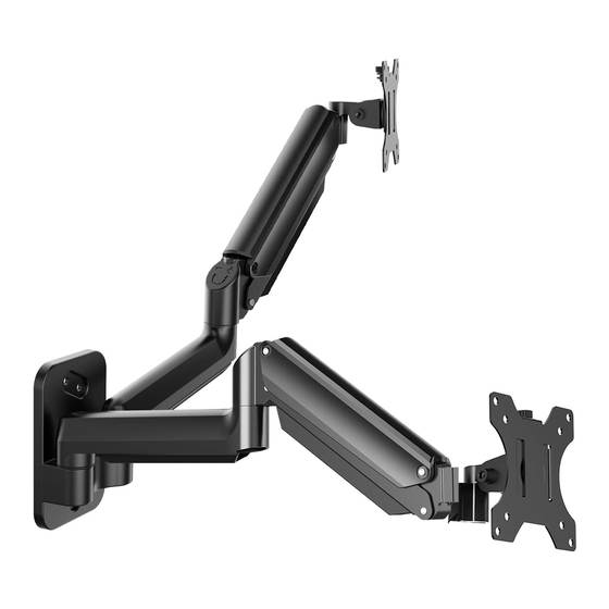
Wall Monitor Arm Instruction Manual
English
- - - - - - - - - - - - - - - - - - - - - - - - - - - - - - -
Deutsch
- - - - - - - - - - - - - - - - - - - - - - - - - - - - - - -
Français
- - - - - - - - - - - - - - - - - - - - - - - - - - - - - - -
Español
- - - - - - - - - - - - - - - - - - - - - - - - - - - - - - -
Italiano
- - - - - - - - - - - - - - - - - - - - - - - - - - - - - - -
日本語
------------------------------- 51-60
Thank you for choosing this HUANUO product! At HUANUO, we strive to
provide you with the best quality products and services in the industry.
Should you have any issues, please don't hesitate to contact us.
Technical Support:
(US/CA) 1-800-556-0533 Mon-Fri 8am - 8pm (CST)
(UK) 44-808-196-3874 Mon-Fri 2pm - 10pm (UTC)
Other Info:
support@huanuoav.com
support_jp@huanuoav.com (JP)
Website: www.huanuoav.com
Model: HNWDS1
Rev00(B)
01- 10
11- 20
21- 30
31- 40
41- 50
Advertisement

Subscribe to Our Youtube Channel
Related Manuals for HUANUO HNWDS1


Summary of Contents for HUANUO HNWDS1
- Page 1 41- 50 日本語 ------------------------------- 51-60 Thank you for choosing this HUANUO product! At HUANUO, we strive to provide you with the best quality products and services in the industry. Should you have any issues, please don't hesitate to contact us.
-
Page 2: Weight Restrictions
IMPORTANT SAFETY INFORMATION • Please carefully read all instructions before attempting installation. If you do not under- stand the instructions or have any concerns or questions, please contact our customer service at support@huanuoav.com. CAUTION: Avoid potential personal injuries and property damage! •... - Page 3 TENSION ADJUSTMENT SHOULD BE DONE ONLY AFTER MOUNT INSTALLATION Do not adjust tension without monitor 1. Ensure monitor has been attached to the mount. 2. Read your monitor box or manual to find out monitor net weig ht. 3. Ensure the net weight of monitor (including accessories) is within 4.4-17.6 Ibs ( 2- 8 kg).
- Page 4 Tools Neede (Not Included) Phillips 5/32 in (4mm) 3/8 in (10mm) Wood Drill Concrete Drill Supplied Parts and Hardware for Step 1 Screw ST5/16 x 2-3/4 in M10x45mm Wall Plate Template [08] X1 [01] Supplied Parts and Hardware for Step 2 15/64 in (6mm) Large Allen Key M- F1(x1)
- Page 5 1a.Wood Stud Option [01] wall plate template [08] . Drill 3 pilot holes using a 5/32 in (4mm) diameter drill bit. Make sure the depth is not less than 2 3/4 in (70mm). [08] 2 3/4 in (70mm) 5/ 32 in (4mm) [01] screws...
- Page 6 1b.Solid Concrete or Concrete Block Option wall plate template [08] [01] Drill 3 pilot holes using a 3/8 in (10mm) diameter drill bit. Make sure the depth is not less than 3 in (75mm). [08] 3 in (75mm) 3/ 8in) screws [01] [01]...
- Page 7 2. Attach the Monitor Plates to the Monitors Bolt length: Verify adequate thread engagement with bolts or bolts/ spacers combination. We recommend thread engagement by at least 5 turns. - Too short will not hold the monitor. - Too long will damage the monitor. Too Short Too Long Correct...
- Page 8 Round [02] M- F1 (Large Allen Key) M- D M- C 3. Secure the Monitors to Arms M- E...
- Page 9 4. Adjust Gas Spring Tension Be sure to keep the arm in horizontal position during adjustment. Or else, it would be difficult to adjust the mount or damage the mount. 1. If the monitor can stay at the desired height by itself, no adjustment needed. 2.
- Page 10 5. Adjust the Tilt Angle 1. Slightly loosen tilts bolt [T]. 2. Adiust monitors to your desired tilt angle. 3. Retighten both tilt bolt [T] to fix the tilt angle. 6. Route the Cables along the Arms...
- Page 12 WICHTIGE SICHERHEITSHINWEISE • Bitte lesen Sie alle Anweisungen sorgfältig durch, bevor Sie versuchen, sie zu installieren. Wenn Sie die Anweisungen nicht verstehen oder Fragen oder Bedenken haben, wenden Sie sich bitte an unseren Kundenservice unter support@huanuoav.com. Hinweis: Vermeiden Sie mögliche Personen- und Sachschäden! •...
- Page 13 DIE SPANNUNGSEINSTELLUNG SOLLTE NUR NACH DER MONTAGE DURCHGEFÜHRT WERDEN. Warnung! Passen Sie die Spannung nicht ohne Display an. 1. Stellen Sie sicher, dass das Display an der Halterung angebracht ist. 2. Lesen Sie die Verpackung oder das Handbuch Ihres Displays, um das Nettogewicht des Displays zu ermitteln.
- Page 14 Benötigtes Werkzeug (nicht enthalten) Kreuzschraubendreher Wasserwaage Bleistift Balkensucher 10mm Bohrer Holzbohrer Betonwand Bohrer Mitgelieferte Teile und Hardware für Schritt 1 Dübel Zugschrauben M10x45mm ST5/16 x 2-3/4 in Wand Platte Vorlage Armbaugruppe [01] [08] X1 Mitgelieferte Teile und Hardware für Schritt 2 Großer Inbusschlüssel M- F1(x1) Monitor platte...
- Page 15 1a. Holz Balken Option Positionieren Sie die Wand Platte Vorlage [08] auf die gewünschte Höhe und richten Sie die Löcher an der Stiftmittellinie aus. Richten Sie die Wand Platte Vorlage [08] aus und markieren Sie die Löcher. Bohren Sie 3 Führungslöcher mit einem Bohrer mit 4mm Durchmesser.
- Page 16 1b. Vollbeton oder Betonblock Option Positionieren Sie die Wand Platte Vorlage [08] auf die gewünschte Höhe und richten Sie die Löcher an der Stiftmittellinie aus. Richten Sie die Wand Platte Vorlage [08] aus und markieren Sie die Löcher. Bohren Sie 3 Führungslöcher mit einem Bohrer mit 10mm Durchmesser. Stellen Sie sicher, dass die Tiefe nicht weniger als 75mm.
- Page 17 2. Befestigen Sie die Monitor platte an Monitor Bolzenlänge: Stellen Sie sicher, dass ein ausreichender Gewindeeingriff mit der bolzen oder der Kombination aus bolzen und Abstandshalter besteht. Wir empfehlen mindestens 5 Umdrehungen des Gewindeeingriffs. - Zu kurz hält das monitor nicht. - Zu lang beschädigt das monitor.
- Page 18 Monitore mit runder Rückseite [02] M- F1 (Großer Inbusschlüssel) M- D M- C 3. Befestigen Sie die Arme an Monitoren SCHWER! Sie benötigen M- E möglicherweise Unterstützung bei diesem Schritt.
- Page 19 4. Passen Sie die Gasfederspannung an Achten Sie darauf, dass der Arm während des Vorgangs der Einstellung in horizontaler Position bleibt. Andernfalls wäre es schwierig, den Wert anzupassen oder zur Beschädigung der Halterung führen. 1. Wenn der Monitor auf der gewünschten Höhe von selbst bleiben kann, keine Anpassung erforderlich.
- Page 20 5. Bitte stellen Sie die Neigung Winkel ein 1. Lösen Sie die bolzen [T] leicht. 2. Stellen Sie das monitor auf den gewünschten Neigungswinkel ein. 3. Ziehen Sie bolzen [T] wieder an, um den Neigungswinkel monitor. 6. Verlegen Sie die Kabel entlang der Arme...
- Page 21 7.Winkeleinstellung Schwenkbar Schwenkbar Schwenkbar Neigbar Drehbar...
- Page 22 Information de sécuritaire importante Veuillez bien lire tous les instructiona avant du montage. Si vous ne comprenez pas les • instructions ou avez des questions, contactez s’ il vous plaît le service client par support@huanuoav.com Attention: évitez les potentiels dommages corporels et aux biens. •...
- Page 23 LE REGLAGE DES TENTIONS NE DOIT ETRE EFFECTUE QU’APRES L’INSTALLATION DU MONTAGE Attention ne pas ajuster la tension sans affichage. 1.s'assurer que l'affichage a été attaché à la monture. 2.lisez l'emtballage ou le manuel de votre présentoir pour connaître le poids net. 3.S'assurer que le poids net de l'écran, ( les accessoires compris) est compris entre 4.4-17.6 lbs (2-8 kgs).
- Page 24 Outils nécessaires (Non Inclus) Détecteur de Poteau crayon Niveau Tournevis cruciform 10mm perçoir Perçoir à bois perçoir à béton Pièces et matériels fournis pour la première étape 1 Ancre Tire- fond M10x45mm ST5/16 x 2-3/4 in Modèle de Plaque Murale Assemblage [08] X1 [01]...
- Page 25 1a. Option de poteau de bois Posez Modèle de Plaque Murale [08] à la hauteur souhaitée et alignez les trous à l’aide de la ligne médiane de votre montant. Mettez la plaque murale de niveau et marquez les trous. Percez3trois par un perçoir de diamètre de 4mm. assurez-vous que la profondeur est moins de 70mm.
- Page 26 1b. Option de Béton Solide ou de Bloc de Béton Posez la Modèle de Plaque Murale [08] à la hauteur souhaitée, nilevez la plaque murale et marquez des emplacements des trous de positionnement. Percez 3 trous de positionnement enutilisant un foret de 10mm de diamètre. Assurez- vous que la profondeur n’ est pas inférieure à...
- Page 27 2. Fixer les Plaque de moniteur aux moniteurs Longueur de boulon: verifier le filet engagé avec les boulons ou la combinaison de boulon et Entretoises. Il est recommandé de engager le filet au moins 5 tours. - Trop court ne supportera pas votre moniteur - Trop longue endommagera votre moniteur Trop court Trop longue...
- Page 28 Moniteur à dos rond [02] M- F1 (Grande clé Allen) M- D M- C 3. Fixer les armes aux moniteurs Lourd!vous auriez M- E besoin d'aide dans cet étape...
- Page 29 4. Régler la Tension du Ressort à Gaz Assurez- vous de garder le bras dans la position horizontale lors du réglage. Sinon, il sera difficile de régler le support ou le support sera endommagé. 1. Si le moniteur peut en lui-même rester à la hauteur souhaitée, le réglage n’est pas nécessaire.
- Page 30 5. Ajuster l'angle d'inclinaison et celui 1. Desserrez doucement les boulon d’ inclinaison [T] 2. Réglez le téléviseur à l’ angle d’ inclinaison souhaité. 3. Serrez de nouveau les boulon d’inclinaison [T] pour fixer l’angle d’inclinaison. 6. Acheminer les Câbles le long des Bras...
- Page 31 7.Ajustement d'angle Pivoter Pivoter Pivoter Incliner Tourner...
- Page 32 INFORMACION DE SEGURIDAD IMPORTANTE Lea atentamente todas las instrucciones antes de intentar la instalación. Si no comprende • las instrucciones o tiene alguna inquietud o pregunta, comuníquese con nuestro servicio al cliente en support@huanuoav.com. PRECAUCIÓN: ¡Evite posibles lesiones personales y daños a la propiedad! •...
- Page 33 EL AJUSTE DE TENSIÓN SE DEBE HACER SOLO DESPUÉS DE LA INSTALACIÓN DEL MONTAJE Advertencia No ajuste la tensión sin la pantalla. 1. Asegúrese de que la pantalla se haya sujetado al montaje. 2. Lea el paquete o manual de la pantalla a encontrar el peso neto de la pantalla. 3.
- Page 34 Herramientas necesarias (no incluidas) Lápiz Nivel Detector de poste Destornillador Phillips 10mm Taladro para Broca para Madera Taladro hormigón Piezas y hardware suministrados para el paso 1 Anclas de Tornillo de retraso pared ST5/16 x 2-3/4 in M10x45mm Plantilla de Placa de Pared Conjunto de brazo [08] X1 [01]...
- Page 35 1a. Opción de Poste de Madera Posicionar la Plantilla de Placa de Pared [08] a la altura deseada y alinear los agujeros con la línea central del poste. Nivelar la placa de pared y marcar los agujeros. Taladrar 3 agujeros piloto usando una broca de diámetro de 4mm. Asegúrese de que la profundidad no sea menos que 70mm.
- Page 36 1b. Opción de Concreto Sólido o Bloque de Concreto Coloque la Plantilla de Placa de Pared [08] de pared a la altura deseada, nivele la Plantilla de Placa de Pared [08] y marque los orificios. Taladre 3 orificios piloto usando una broca de diámetro de 10mm.
- Page 37 2. Asegure los Placa de monitor a los monitores Longitud del Pernos : Verifique el enganche adecuado de la rosca con pernos o combinación de pernos/ espaciadores. Recomendamos el enganche del hilo al menos 5 vueltas. - Demasiado corto no sostendrá el monitor. - Demasiado tiempo dañará...
- Page 38 Monitor trasero redondo [02] M- F1 (Llave Allen grande) M- D M- C 3. Asegure los brazos a los monitores ¡PESADO! Es posible M- E que necesite ayuda con este paso.
- Page 39 4. Ajuste la Tensión del Resorte de Gas Asegurarse de mantener el brazo en la posición horizontal durante el ajuste. De lo contrario, será difícil ajustar el montaje o hará daños al soporte. 1. Si el monitor puede mantenerse a la altura deseada por sí mismo, no se necesita ajuste.
- Page 40 5. Ajuste la inclinación y el ángulo 1. Aflojar ligeramente los perno de inclinación [T]. 2. Ajustar el TV al ángulo de inclinación deseado. 3. Volver a apretar los perno de inclinación [T] para fijar el ángulo de inclinación. 6. Pasar los Cables a lo Largo del Brazo...
-
Page 41: Ajuste De Ángulo
7.Ajuste de ángulo Girar Girar Girar Inclinar Rotar... - Page 42 INFORMAZIONI IMPORTANTI DI SICUREZZA Si prega di leggere attentamente tutte le istruzioni prima dell'installazione. Se non si • comprendono le istruzioni o si hanno dubbi o domande, contattare il servizio clienti all'indirizzo support@huanuoav.com. ATTENZIONE: Evitare potenziali lesioni personali e danni materiali! •...
- Page 43 L'ADATTAMENTO DELLA TENSIONE DEVE ESSERE EFFETTUATO SOLO DOPO L'INSTALLAZIONE DEL MONTAGGIO Attenzione Non regolare la tensione senza display 1. Assicurarsi che il display sia stato collegato al supporto. 2. Leggere l'imballaggio dello schermo o il manuale per scoprire il peso netto del display.
- Page 44 Strumenti necessari (non inclusi) Matita Cacciavite a croce Livello Rilevatore Digitale 10mm Trapano Punta Legno Punta Cemento Parti e Hardware Forniti per il Passaggio 1 Viti Lag Ancore a muro ST5/16 x 2-3/4 in M10x45mm Modello dipiastra a parete Gruppo di Braccio [08] X1 [01] Parti e Hardware Forniti per il Passaggio 2...
- Page 45 1a. Opzione di borchia legno Posizionare il gruppo di Modello dipiastra a parete [08] all'altezza desiderata e allineare i fori con la linea centrale del perno. Livellare il Modello dipiastra a parete [08] e contrassegnare i fori. Trapanare 3 fori pilota con una punta da 4mm di diametro. Assicurarsi che la profondità...
- Page 46 Opzione per calcestruzzo solido o blocco di calcestruzzo Posizionare il Modello dipiastra a parete [08] all'altezza desiderata, livellare la piastra a parete e contrassegnare le posizioni dei fori pilota. Praticare 3 fori pilota con una punta di diametro 10mm. Assicurarsi che la profondità non sia inferiore a 75mm. Non perforare mai la malta tra i blocchi.
- Page 47 2. Fissare i Piastra Monitor ai monitor Lunghezza bullone: verificare il corretto avvitamento con le combinazioni di bulloni o bulloni/ distanziali. Si raccomanda l'avvitamento di almeno 5 giri. - Se troppo corto non terrà la monitor. - Se troppo lungo danneggerà la monitor. Troppo Troppo corto...
- Page 48 Monitor con Retro a Curva [02] M- F1 (Chiave a Brugola Grande) M- D M- C 3. Fissare i Bracci ai monitor PESANTE! Potrebbe M- E essere necessaria assistenza per questo passaggio...
- Page 49 4. Regolare la tensione della molla a gas Assicurarsi di mantenere il braccio in posizione orizzontale durante la regolazione, altrimenti sarebbe difficile regolare il supporto o danneggiarlo. 1. Se il monitor può rimanere all'altezza desiderata da solo, non è necessaria alcuna regolazione.
- Page 50 5. Regolare l'inclinazione e l'angolo 1. Allentare leggermente i bulloni d’ inclinazione [T]. 2. Regolare il televisore all’ angolo d’ inclinazione desiderato. 3. Reserrare i bulloni d’inclinazione [T] per fissare l’angolo d’inclinazione. 6. Instradare i cavi attorno ai bracci...
-
Page 51: Regolazione Dell'angolo
7.Regolazione dell'Angolo girare girare girare Inclinazione rotare... - Page 52 安全上のご注意 • 組み立てる前に必ずこのマニュアルをよくお読みになり、正しくお使ってください。取り付け や取扱説明書に何かご不明な点がございましたら、専門知識のある業者の方にご依頼してくだ さい。連絡先:support_jp@huanuoav.com • 当商品は木柱間壁、コンクリート壁、コンクリートブロック壁やレンガ壁に対応しています。 下地ない石膏ボード壁に取り付けないでください。付属の部品をすべて使用するわけではあり ません。 • 設置の際は取扱説明書で記載される以外の使用目的で使用しないでください。最大耐荷重を超 えないでください。取り付け不備や、取り扱い不備による事故や損傷については、当社では一 切の責任を負いません。 • 当製品内部が高圧ガススプリングが含まれているため、火気•暖房器具•熱具に近づけないでく ださい。本製品を分解、改造しないでください。不用品回収をプロに依頼してください。 • モニターアームを取り付けるデスクは、モニターとモニターの総重量の3 倍の重量を、保持す る強度が必要です。当製品をパーチクルボードに使用しないでください。 耐荷重制限 警告 2.0- 8.0 kg 最大耐荷重以上のモニターの取り付けには絶対使用しない でください。この指定を守らないと、ディスプレイが落下 して、けがをしたり、ディスプレイが破損する原因となり ます。 モニターの重量は8kg を超えないようにして ください。 取り付ける前にモニターのVESA規格確認 最小VESA規格:75mm(横)x75mm(縦) ご注意: お持ちのモニターVESA規格は75mmx75mm未満、100mmx100mm を超える場合は、当商品はお持ちのモニターに対応していますせん。 当商品はお持ちのモニターに不適合な場合は、アフターサービスに連絡して、 適合の壁かけ金具をおすすめです。連絡先:support_jp@huanuoav.com...
- Page 53 モニターを取り付けされた後で、張力を調節してください。 ご注意 アームにモニターをかけるところに張力を調節してください。 1.モニターをマウントにしっかり取り付けるのをご確保ください。 2.当製品の耐荷重は8kgです。お持ちのモニターは当製品の耐荷重の範囲内であ ることをご確認の上、使用してください。 調節サイン 軽いモニターの場合、時計回り 重いモニターの場合、反時計回り に回して、張力を減らします。 に回して、張力を増やします。 (負荷を高める) ご注意...
- Page 54 必要な工具類(別売) フィリップス ペン 水準器 下地センサー ドライバー 10mm ドリル 木材ドリル コンクリートドリル 手順1に使用される部品 ラグネジ 壁アンカー ST5/16 x 2-3/4 in M10x45mm アーム ・ 壁プレート 底板テンプレート [08] X1 [01] 手順2に使用される部品 大六角レンチ M- F1(x1) 底板 [02] ボルト スペーサー ワッシャー ボルト L13mm M4x30mm (x8) M- B 手順3や5に必要な取り付ける部品...
- Page 55 1a. 木柱壁面の場合 底板テンプレート[08]をご希望の高さに置き、下穴を開ける位置が柱の中心位置に来るように位 置決めします。その後、底板テンプレート[08]を水準器で水平度を確認しながら、図のように3 か所に印を付けます。下穴は、4mmドリルで穴に三箇所を開けます。深さが最低70mmである ことを確保してください。 [08] 70mm ラグネジ[W-A]で壁プレート[01]を取り付けます。 [01] W- A この手順でアンカーを使用しないでください。 13mm ソケットレンチ (別売)...
- Page 56 コンクリート又はコンクリートブロック壁面の場合 アーム・壁プレート[01]をお好みの高さで水平に仮置きにして、下穴を開ける位置に印を付けま す。10mmドリルで穴に三箇所を開けます。深さが最低75mmであることを確保してください。ブ ロックの間隔にドリルしないでください。 [08] 75mm 図の順番でラグネジ[W-A]でアーム・壁プレート[01]を取り付けます。 コンクリートド リルで絶対穴を 開けないでくだ さい。 [01] 13mm ソケットレンチ (別売)...
- Page 57 2. モニターにVESA プレートを取り付ける ボルト長さについて:必要に応じて、複数のスペーサーを積み重ねて使用するのは可能です。 また、お持ちのモニターに適合しない場合は、ぜひこちらに連絡してください。 -ボルトが短すぎる場合はモニターを固定できません。 -ボルトが長すぎる場合はモニターを破壊します。 短すぎる 長すぎる 適合 適合 背面が平坦なモニター [02] M-F1 (大六角レンチ) M- C...
- Page 58 背面が湾曲なモニター [02] M-F1 (大六角レンチ) M- D M- C モニターをアームに取り付ける ご注意:この作業は重量 M- E 物を取り扱うので、二人 以上で行ってください。...
- Page 59 4. ガススプリングを調節する 張力を調節しているときに、アームを水 平にしてください。マウントを調節しが たく、マウントに損害がある可能性が高 いです。 1.モニターを取り付けされた後で、任意の位置で固定できる場合は、ガススプリングを調 節する必要がありません。 2.取り付けされた後でモニターが上がる場合は、モニターを水平にするために手で下に押 し付けて、六角レンチ[T2]で「-」方向にアームをお好みの位置で固定できるまでにボル トを時計回して張力を減します。 3.取り付けされた後でモニターが垂れる場合は、モニターを水平にするために手で上に持 ち上げて、六角レンチ[T2]で「+」方向にアームをお好みの位置で固定できるまでにボル トを反時計回して張力をは増やします。 M-F1 (大六角レンチ)
- Page 60 5. ティルト調節 1. 事前に取り付けたボルト[T]を少し緩めます。 2. モニターをご希望の角度に調整します。 3. ボルト[T]を締め直して、モニターを所定の位置に固定します。 6. アームに沿わせてケーブルを配線...
- Page 61 7.回転調節 スイベル スイベル スイベル ティルト 回転...
- Page 64 Thank you again choosing this HUANUO product! All of us at HUANUO do appreciate your product purchase. We hope that you are as happy with your product as we designing and manufacturing it for you. We strive to provide you with the best quality products and services in the industry.
Need help?
Do you have a question about the HNWDS1 and is the answer not in the manual?
Questions and answers