Advertisement
Quick Links
Website:
www.huanuoav.com
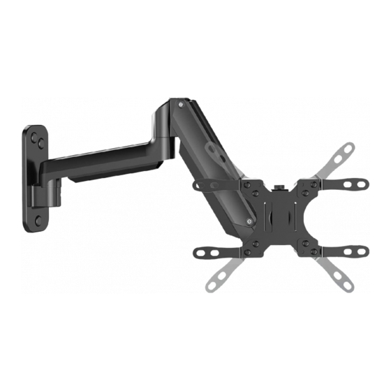
Monitor Wall Mount
Instruction Manual
Model: HNWSS1
Thank you for choosing this HUANUO product! At HUANUO
we strive to provide you with the best quality products and
services in the industry. Please share your experience of our
product with others at www.huanuoav.com/reviews if you
are satisfied. Should you have any issues, please don't
hesitate to contact us.
Technical Support:
1-800-556-0533 Mon-Fri 10am - 5pm (PST) (USA) (CAN)
Other Info:
support@huanuoav.com (US/CA)
V1.0
V1.0
Advertisement

Related Manuals for HUANUO HNWSS1


Summary of Contents for HUANUO HNWSS1
- Page 1 V1.0 V1.0 Model: HNWSS1 Thank you for choosing this HUANUO product! At HUANUO we strive to provide you with the best quality products and services in the industry. Please share your experience of our product with others at www.huanuoav.com/reviews if you are satisfied.
-
Page 2: Important Safety Information
IMPORTANT SAFETY INFORMATION • Please carefully read all instructions before attempting installation. If you do not understand the instructions or have any concerns or questions, please contact our customer service at support@huanuoav.com CAUTION: Avoid potential personal injuries and property damage! •... - Page 3 Verify Your Wall Construction If you are not sure the wall CAUTION construction, please contact our product DO NOT support line at install into 1-800-556-0533 or drywall alone customer service at Wood Studs Solid Concrete support@huanuoav.com (with Drywall) or Concrete Block Tools Needed (Not lncluded) Tape Measure Drill...
- Page 4 Supplied Parts and Hardware for Step 2 Washer Spacers [If needed] Note: The washer and spacers are shown in accordance with the actual size Spacer Washer M-F x4 M-E x4 Bolts Monitor [Only one bolt size fits your monitor] Note: The bolts are shown in accordance with the actual size M4 x 12mm M4 x 16mm M-A x4...
- Page 5 Washer W-B x3 Wall Anchor M10x45mm W-C x3 Supplied Parts and Hardware for Step 4 and Step 5 Small Allen Key Large Allen Key Bolt 5/32in.(4mm) 15/64in.(6mm) I x1 T1 x1 T2 x1 Choose the Combination that Applies to Your VESA Hole Step 1 Pattern (3.94 in.)
- Page 6 Secure the Faceplate [02] or Faceplate [02] with Step 2 Extender Brackets [03 and 04] to Monitor Select Monitor Bolts Only one bolt size fits your monitor. Bolt length: Verify adequate thread engagement with bolts or bolts/spacers combination. We recommend thread engagement by at least 5 turns. -Too short will not hold the monitor.
- Page 7 Option B (For Round Back Monitor) M-B/M-C/M-D (If Needed) Option C (For Monitor with A “Bump”) Spacers may be necessary for 2 holes ONLY. M-A/M-C /M-D (If Needed) M-B/M-C/M-D (If Needed) (If Needed) Option D For cable interference or inset holes, use spacers to create extra space between the monitor and faceplate...
- Page 8 Step 3 Attach the Arm Assembly/Wall Plate [01] to Wall For wood stud installation, follow STEP 3A For concrete installation, follow STEP 3B Step 3A Wood Stud Option WARNING: ●Avoid potential personal injury or property damage! DO NOT over-tighten the lag screws [W-A] and washers [W-B].
- Page 9 3A-3 Drill 3 pilot holes using a 5/32 in.(4 mm) diameter drill bit. Make sure the depth is not less than 2 11/64 in.(55mm). 2 11/64 in.(55mm) ø5/32 in.(4mm) 3A-4 Install the arm assembly/wall plate [01] using lag screws [ ] and washers [ ].
- Page 10 3B-1 Position arm assembly/wall plate [01] at your desired height, level arm assembly/wall plate [01] and mark the pilot hole locations. 3A-2 Drill 3 pilot holes using a 3/8 in.(10mm) diameter drill bit. Make sure the depth is not less than 2 23/64 in.(60mm).
- Page 11 Step 4. Hang the Monitor to the Mount You may need assistance with this step. Step 5. Gas Spring Tension and Tilt Adjustment Gas Spring Tension Adjustment Be sure to keep the arm in horizontal position during adjustment. Or else, it would be difficult to adjust the mount or damage the mount.
- Page 12 Step 6. Route the Cables along the Arm Angle Adjustment...
Need help?
Do you have a question about the HNWSS1 and is the answer not in the manual?
Questions and answers