Advertisement
Quick Links
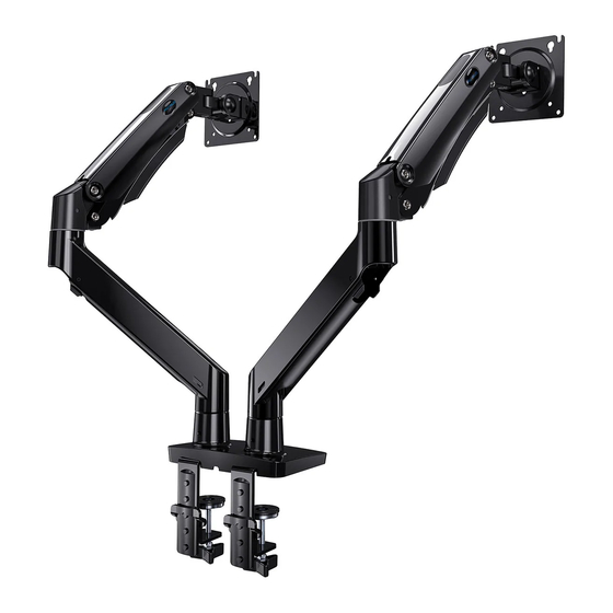
Monitor Desk Mount
Instruction Manual
English
Deutsch
Français
Español
Italiano
日本語
Website:
www.huanuoav.com
------------------------ 01-10
------------------------ 11-19
------------------------ 20-28
------------------------ 29-37
------------------------ 38-46
------------------------ 47-55
Thank you for choosing this HUANUO product! At HUANUO we
strive to provide you with the best quality products and services in
the industry. Please share your experience of our product with
others at www.huanuoav.com/reviews if you are satisfied. Should
you have any issues, please don't hesitate to contact us.
Technical Support:
1-800-556-0533 Mon-Fri 10am - 5pm (PST) (USA) (CAN)
Other Info:
support@huanuoav.com (US/CA)
support_eu@huanuoav.com(DE/UK/FR/IT/ES/NL/SE/AU)
support_jp@huanuoav.com(JP)
Model: HNDS12
V4.0
Advertisement

Related Manuals for HUANUO HNDS12


Summary of Contents for HUANUO HNDS12
- Page 1 ------------------------ 38-46 日本語 ------------------------ 47-55 Thank you for choosing this HUANUO product! At HUANUO we strive to provide you with the best quality products and services in the industry. Please share your experience of our product with others at www.huanuoav.com/reviews if you are satisfied. Should you have any issues, please don't hesitate to contact us.
- Page 2 IMPORTANT SAFETY INFORMATION Please carefully read all instructions before attempting installation. If you do not understand the instructions or have any concerns or questions, please contact our Technical Support line at 1-800-556-0533 or customer service at support@huanuoav.com CAUTION: Avoid potential personal injuries and property damage! •...
- Page 3 Product Features C-Clamp Mounting 32 in. ~ 3 35 64 in. (20~90mm) Grommet Mounting 32 in. ~ 3 35 64 in. (20~90mm)
- Page 4 TENSION ADJUSTMENT SHOULD BE DONE ONLY AFTER MOUNT INSTALLATION Do not adjust tension without monitor. 1. Ensure monitor has been attached to the mount. 2. Read your monitor box or manual to find out monitor net weight. 3. Ensure the net weight of monitor (including accessories) is between 4.4~26.5 Ibs (2-12 kg).
- Page 5 Tools Needed (Not lncluded) Drill Bit Electric Drill (Optional) (Optional) 0.4 in.(10mm) - 2 in.(50mm) Phillips Screwdriver Supplied Parts and Hardware Warning:This product contains small items that could be a choking hazard if swallowed. Before starting assembly, verify all parts are included and undamaged. Do not use damaged or defective parts.
-
Page 6: Install The Base
Supplied Parts and Hardware for Step 4 Bolt Bolt 5mm Spacer M4x12mm M4x16mm B-2 (x8) A (x8) B-1 (x8) Supplied Hardware for Step 5 and Step 7 13/64 in.(5mm) Large Allen Key F (x1) 1. Install the Base A. For Clamp Mounting Medium Allen Key Warning:... - Page 7 25/64 in.~ 3 35/64 in. 25/32 in.~ 3 35/64 in. 10~90mm 20~90mm B. For Grommet Mounting Warning: Ensure bolt is secured firmly. If there is no grommet hole on your desk, position the base [05] on the mounting surface and mark the hole. Drill a hole using the drill bit in a diameter of 0.4 Ensure nut is in.(10mm) - 2 in.(50mm) at the marked position...
- Page 8 2. Install the Arms and Arm Extensions to Base Small Do not over-tighten set the Allen Key screw [M] in order not to affect the rotation of the arm. Small Allen Key 3. Install the Monitor Plate to Arms Large Allen Key Attach the monitor plate [06] from the sides of the top end of arm [01], then secure the...
- Page 9 4. Attach Monitors to the Arm 4-1 Choose Proper Bolts 4-2 Install Monitors to the Arms Flat back monitor Phillips 0.1-0.2in.(3-5mm) spacing left Screwdriver [Not Included] Curved back monitor The tension is preset at 8.8-11 LBS(4-5kg). After hanging the monitor to the mount, please release the monitor slowly to 75 mm ≈...
- Page 10 Large Allen Key 6. Rotation Restriction Proper usage directions Non-proper usage directions 7. Tilt Adjustment 4. Route Cables along the Arm Adjust monitor to proper tilt angle. Use Allen key (F) to tighten the bolt and fix tilt angle Large Allen Key...
- Page 11 8. Route Cables along the Arms Pull down the groove part along the arm to detach the cover from the Pinch the both sides of the top end of the cover to make it attach to the arm...
Need help?
Do you have a question about the HNDS12 and is the answer not in the manual?
Questions and answers