Table of Contents
Advertisement
Quick Links
Monitor Desk Mount Instruction Manual
Website:
www.huanuoav.com
Model: HNSS8
Thank you for choosing this Huanuo product! At Huanuo we strive to
provide you with the best quality products and services in the
industry. Please share your experience of our product with others at
www.huanuoav.com/reviews if you are satisfied. Should you have
any issues, please don't hesitate to contact us.
Technical Support:
1-800-556-0533 Mon-Fri 10am - 5pm (PST) (USA) (CAN)
Other Info:
supporteu@huanuoav.com (DE/UK/FR/IT/ES/AU)
support@huanuoav.com(US/CA)
V3.0
Advertisement
Table of Contents

Subscribe to Our Youtube Channel
Related Manuals for HUANUO HNSS8


Summary of Contents for HUANUO HNSS8
- Page 1 Monitor Desk Mount Instruction Manual V3.0 Model: HNSS8 Thank you for choosing this Huanuo product! At Huanuo we strive to provide you with the best quality products and services in the industry. Please share your experience of our product with others at www.huanuoav.com/reviews if you are satisfied.
-
Page 2: Weight Restrictions
IMPORTANT SAFETY INFORMATION Please carefully read all instructions before attempting installation. If you do not understand the instructions or have any concerns or questions, please contact our Technical Support line at 1-800-556-0533 or customer service at support@huanuoav.com CAUTION: Avoid potential personal injuries and property damage! •... -
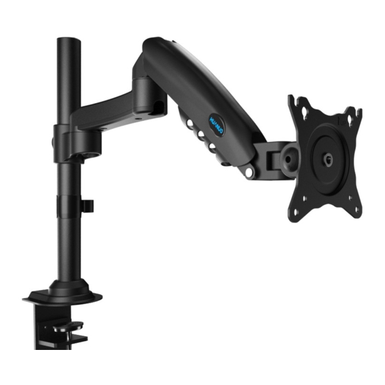
Page 3: Product Features
Product Features C-Clamp Mounting Grommet Mounting... - Page 4 TENSION ADJUSTMENT SHOULD BE DONE ONLY AFTER MOUNT INSTALLATION Do not adjust tension without monitor 1. Ensure monitor has been attached to the mount. 2. Read your monitor box or manual to find out monitor net weight. 3. Ensure the net weight of monitor (including accessories) is between 4.4~19.8 Ibs (2-9 kg).
- Page 5 Tools Needed (Not lncluded) Screwdriver Supplied Parts and Hardware Warning :This product contains small items that could be a choking hazard if swallowed. Before starting assembly, verify all parts are included and undamaged. Do not use damaged or defective parts. lf you require replacement parts, contact our customer service at support@huanuoav.com •...
- Page 6 Supplied Parts and Hardware for Step 2 Arm X1 Cable Clip X1 5/32 in.(4mm) Allen Key Supplied Parts and Hardware for Step 3 Bolt (A) Bolt (B-1) Spacer (B-2) M4x12mm (4pcs) M4x16mm (4pcs) 5mm (4pcs) Supplied Parts and Hardware for Step 4 and Step 6 13/64 in.(5mm) Allen Key Supplied Parts and Hardware for Step 8...
-
Page 7: Step 1 Install The Base
Step 1 Install the Base A. For Clamp Mounting A-1 Install the C-Clamp Connect part [X] to pole Warning: assembly [03] Ensure bolts are secured firmly. Detach the c-clamp entirely ① 5/32 in. ② (4mm) Connect part [Y] to part [X] according to the thickness of the desktop The second choice The first choice Secure the base to the desktop... - Page 8 B. For Grommet Mounting 1 Install the grommet bolt Warning: Ensure bolts are secured firmly. Secure the base to desktop using locking plate [E] and butterfly nut [D] Warning: Ensure bolts are secured firmly.
- Page 9 Step 2 Install the Arms Slide the cable clip [05] to the pole assembly [03] Slide arm [01] to the pole assembly [03] Secure the arm [01] to the pole assembly [03] by tightening the preassembled bolts on the arm [01] Ensure bolts are secured firmly.
- Page 10 Step 3 Attach Monitor to the Arm 3-1 Choose Proper bolts 3-2 Install Monitors to the Arms Flat back monitor 0.1-0.2in.(3-5mm) spacing left Screwdriver [Not Included] Round back monitor The tension is preset at 8.8~11 Ibs(4-5kg). After hanging the monitor to the mount,please release the monitor slowly to prevent it from falling suddenly.
- Page 11 13/64 in. (5mm) (1 rotation ≈ 1 lb) Step 5 Rotation Restriction Proper usage directions Non-proper usage directions...
-
Page 12: Step 6 Tilt Adjustment
Step 6 Tilt Adjustment 13/64 in. (5mm) “+” Clockwise: Tighten “-” Counter-clockwise: Loosen Situation 1: If the monitor can stay at the desired tilt angle by itself, no adjustment needed. Situation 2: If the monitor can not stay at the desired tilt angle by itself, turn the bolts clockwise or counter-clockwise as shown until the monitor can stay at the desired tilt angle by itself. - Page 13 Step 8 Route Cables along the Arm Screwdriver [Not Included] Secure the Cable Cover [04] to the arm [01] by tightening the bolts [G] using screwdriver Loosen the preassembled bolts [S] on the Route the cables into the cable guide and arm [01] to detach the cable guide from the secure the cable guide by tightening the arm [01], and keep the bolt for the use in...
- Page 14 Put the cables into the cable clip [05]...
Need help?
Do you have a question about the HNSS8 and is the answer not in the manual?
Questions and answers