Table of Contents
Advertisement
Quick Links
Advertisement
Table of Contents

Related Manuals for Panduit ATLONA OMEGA AT-OME-CS31-SA


Summary of Contents for Panduit ATLONA OMEGA AT-OME-CS31-SA
- Page 1 AV Presentation and Collaboration System Atlona Manuals AT-OME-CS31-SA Switchers...
- Page 2 Version Information Version Release Date Notes Mar 2024 Initial release AT-OME-CS31-SA...
- Page 3 Sales, Marketing, and Customer Support Main Office International Headquarters Atlona Incorporated Atlona International AG 70 Daggett Drive Tödistrasse 18 San Jose, CA 95134 8002 Zürich United States Switzerland Office: +1.408.962.0515 Office: +41.43.508.4321 Sales and Customer Service Hours Monday - Friday: 6:00 a.m. - 4:30 p.m. (PST) Sales and Customer Service Hours Monday - Friday: 09:00 - 17:00 (UTC +1) https://atlona.com/...
- Page 4 Safety and Certification The lightning flash with arrowhead symbol, within an equilateral triangle, is intended to alert the user to the presence of uninsulated “dangerous voltage” within the product’s enclosure that may be of sufficient magnitude to constitute a risk of electric shock to persons. Das Symbol des Blitzzeichens innerhalb eines gleichseitigen Dreiecks soll den Benutzer davor warnen, dass innerhalb des Gehäuses gefährlich hohe Spannung an berührbaren Teilen anliegt.
- Page 5 Safety and Certification 9. Do not defeat the safety purpose of a polarized CAUTION or grounding-type plug. A polarized plug has two RISK OF ELECTRIC SHOCK blades with one wider than the other. A grounding DO NOT OPEN type plug has two blades and a third grounding CAUTION: TO REDUCT THE RISK OF prong.
-
Page 6: Table Of Contents
Table of Contents Introduction Features Package Contents Panel Description Front Panel Rear Panel Installation Connection Instructions Connection Diagram IP Configuration Obtaining the Current IP Address Automatic Private IP Addressing (APIPA) Mode Device Operation LED Indicators Logging in to the Web Server Login Registration Logging in after Registration System Configuration... - Page 7 Table of Contents Display Control Using CEC RS-232 Configuration TCP/IP Configuration Completing RS-232 or IP Configuration System Settings System Standby Locking / Unlocking the Front Panel Blink Resetting to Factory-Default Settings Performing a System Reboot API Testing Exporting the System Log Exporting the System Configuration Importing a System Configuration File Configuration and Management Interfaces...
-
Page 8: Introduction
Introduction The Atlona AT-OME-CS31-SA is an AV presentation and collaboration system for classrooms and conference rooms. It features a 3x1 HDMI switcher, 50 watt mixer amplifier, and USB 3.0 hub. ® The HDMI switcher is HDCP 2.2 compliant and supports up to 4K/60 4:4:4 plus HDR formats for common inputs such as laptops, computers, and document cameras routed to the output connected to a projector or display. -
Page 9: Features
Features • 3x1 HDMI® switcher for common source devices such laptops, computers, and document cameras as well as output to a projector or display. • Integrated USB hub with two 3.0 type B host ports and four 3.0 type A peripheral ports. •... -
Page 10: Panel Description
Panel Description Front Panel SWITCHER WITH AUDIO AMPLIFIER AT-OME-CS31-SA INPUT HDMI IN HOST AUDIO IN CLASS 2 WIRING TRIGGER LED Indicators VOICE L/R These LED indicators provide information about the Connect the included 5-pin captive screw connector TRIGGER I/O RS-232 PA SENSE AMP OUT AUDIO OUT... -
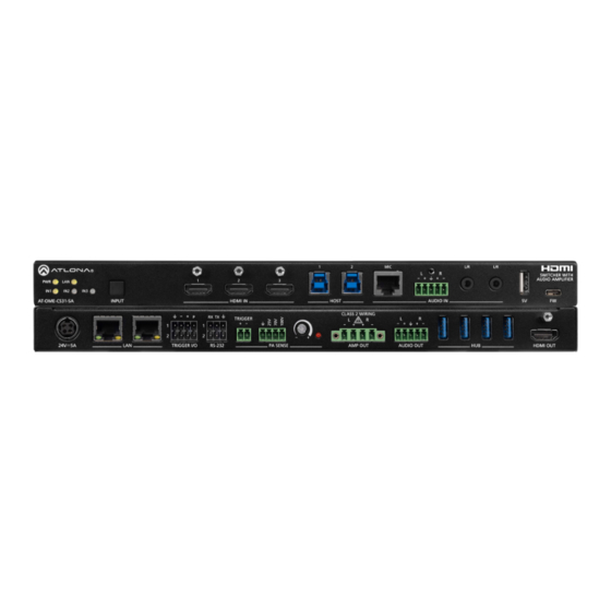
Page 11: Rear Panel
Panel Description Rear Panel SWITCHER WITH AUDIO AMPLIFIER AT-OME-CS31-SA INPUT HDMI IN HOST AUDIO IN CLASS 2 WIRING TRIGGER TRIGGER I/O RS-232 PA SENSE AMP OUT AUDIO OUT HDMI OUT 24V / 5A GND/25V/75V/100V (PA SENSE) Connect the included 24 V / 5 A power supply from Connect the included 4-pin captive screw connector this port to an available AC electrical outlet. -
Page 12: Installation
Installation Connection Instructions 1. Connect an HDMI cable from a source to these HDMI IN ports. 2. Connect an HDMI cable from the HDMI OUT port to a local display. 3. Connect a USB cable from the HOST port to the host USB device. 4. -
Page 13: Connection Diagram
Installation Connection Diagram Wireless Public Address Microphone System Assistive Listening System Laptop G en R SYS Laptop G en R SYS Speakers PL IFI DI O M IC DI O IN PU CS 31 M E- AT -O AT-OME-CS31-SA B 2.0 B 3.0 AT-WAVE-101 AT-VKP-8E... -
Page 14: Ip Configuration
Installation IP Configuration The AT-OME-CS31-SA is shipped with DHCP enabled. Once connected to a network, the DHCP server (if available), will automatically assign an IP address to the unit. If the AT-OME-CS31-SA is unable to detect a DHCP server within 15 seconds, then the unit will use a self-assigned IP address within the range of 169.254.xxx.xxx/16. -
Page 15: Device Operation
Device Operation LED Indicators The LED indicators on both the front and rear of the unit provide basic information on the current status of the AT-OME-CS31-SA. State Description Solid green Unit is powered and in normal operating mode. Solid red Indicates there is a fault during power up. -
Page 16: Logging In To The Web Server
Device Operation Logging in to the Web Server Most of the AT-OME-CS31-SA operation is handled through the built-in web server. In order to access the web server, the IP address of the unit must be known. Login Registration Before the built-in web server can be accessed, a password must be created. 1. -
Page 17: Logging In After Registration
Device Operation 6. Enter the desired password in the Admin Password field. NOTE: Passwords can be 5 to 32 characters in length and can only contain letters, numbers, dashes, underscores, and periods. 7. Click the Save button. 8. The System > Info page will be displayed. Logging in after Registration 1. -
Page 18: System Configuration
Device Operation System Configuration The AT-OME-CS31-SA provides easy access to system configuration through the built-in web server, and is the recommended method to adjust network settings. Getting the MAC Address 1. Log in to the web server. 2. Click System > Network in the menu bar. 3. - Page 19 Device Operation 3. Locate the IP Mode toggle switch. The default setting of this toggle switch is DHCP. 4. Click this toggle switch to set it to Static. 5. Enter the desired IP address for the AT-OME-CS31-SA in the IP field. 6.
-
Page 20: Changing The Telnet Port
Device Operation Changing the Telnet Port Typically, the Telnet service is assigned to TCP port 23. This is the default setting for the AT-OME-CS31-SA. However, depending upon the network environment, the default Telnet port can be changed. The Telnet port can be changed independently of the IP mode. -
Page 21: Setting The Host Name
Device Operation Setting the Host Name By default, the AT-OME-CS31-SA is assgned a hostname, which is constructed as follows: CS31-[last six digits of MAC address] For example, a default hostname might look like this: CS31-0EF463. This value can be changed to easily identify the AT-OME-CS31-SA within Velocity Device Manager or on a network. -
Page 22: Auto Switching
Device Operation Auto Switching The AT-OME-CS31-SA provides Auto Switching capability, which is enabled by default. This feature will automatically switch the input to the most recently-connected source. If the active source is disconnected, then the input will automatically be switched to the previously-connected source. Enabling / Disabling Auto Switching By default, Auto Switching is enabled on the AT-OME-CS31-SA, allowing the unit to automatically switch between inputs when sources are connected or disconnected. -
Page 23: Setting The Fallback Input
Device Operation Setting the Fallback Input If the previously active input is no longer available, then the AT-OME-CS31-SA will switch to the input that is selected in the Fallback Input drop-down list. 1. Log in to the web server. 2. Click Video > A/V Routing in the menu bar. 3. -
Page 24: Input Switching
Device Operation Input Switching Switching between inputs can be performed using the front panel or through the built-in web server. Using the Front Panel 1. Make sure the AT-OME-CS31-SA is powered. 2. Press and release the INPUT to cycle through each input: IN1, IN2, and IN3. Press the INPUT button again to display the Info screen (see Figure 1.1). -
Page 25: Using The Web Server
Device Operation Using the Web Server 1. Connect an Ethernet cable between the LAN port of the AT-OME-CS31-SA and the Local Area Network (LAN). 2. Log in to the web server. 3. Click Video > A/V Routing in the menu bar. 4. -
Page 26: Hdcp Content
Device Operation HDCP Content Transmitting HDCP content to a display that is not HDCP compliant can result in “snow”, image flickering, or no picture. In the illustration below, a laptop source is connected to the AT-OME-CS31-SA, which is connected to a display that is not HDCP compliant. -
Page 27: Edid Management
Device Operation EDID Management Before a source can send picture and sound to a display device, the source reads the EDID (Extended Display Identification Data) stored in the display. The EDID contains information about what type of video and audio formats are supported by the display. -
Page 28: Edid Presets
Device Operation EDID Presets The AT-OME-CS31-SA provides the option of selecting a preset EDID. The following presets are available. EDID Description Connected Display Uses the downstream EDID of the connected display ATL 3840x2160@60 2CH HDR PCM 3840 x 2160 @ 60 Hz w/ 2-channel audio / HDR / Linear PCM ATL 3840x2160@30 2CH SDR PCM 3840 x 2160 @ 30 Hz w/ 2-channel audio / SDR / Linear PCM ATL 1920x1080P@60 2CH SDR PCM... -
Page 29: Storing Edid Data
Device Operation Storing EDID Data The AT-OME-CS31-SA provides a blank memory location that can be used to store EDID data. Any downstream EDID can be captured and stored in this location. This memory location is non-volatile and captured EDID data is stored after power is disconnected from the unit. - Page 30 Device Operation 6. Once the EDID has been captured, the following message will be displayed near the bottom of the screen. 7. Click any of the input drop-down list boxes. Note that the stored EDID appears as an available EDID preset for each available input on the AT-OME-CS31-SA.
-
Page 31: Downloading Edid Data
Device Operation Downloading EDID Data The AT-OME-CS31-SA can download the EDID from the HDMI OUT port. 1. Connect an HDMI cable from the HDMI OUT port on the AT-OME-CS31-SA to the HDMI input on the display, containing the EDID to be stored. 2. -
Page 32: Importing Edid Data
Device Operation Importing EDID Data Imports a .bin file, containing EDID data, to be loaded into the AT-OME-CS31-SA. 1. Log in to the web server. 2. Click Video > EDID in the menu bar. 3. Locate the EDID Saved section. 4. -
Page 33: Pa Sense
Device Operation PA Sense This section covers PA sense, which mutes the current audio program for the duration of a PA broadcast. The AT-OME-CS31-SA provides two options to trigger PA sense: 1) by tapping into the speaker wire or 2) using the TRIGGER port. Tapping into the Speaker Wiring 1. -
Page 34: Connecting To A Paging Sensor
Device Operation Connecting to a Paging Sensor INPUT INPUT HDMI IN HDMI IN HOST HOST AUDIO IN AUDIO IN 1. Connect the included 2-pin captive screw connector from the TRIGGER port to the paging sensor. CLASS 2 WIRING CLASS 2 WIRING TRIGGER TRIGGER TRIGGER I/O... -
Page 35: Usb Routing And Management
Device Operation USB Routing and Management The AT-OME-CS31-SA provides two different USB modes: Follow Video, and Manual. Each mode provides a different method of controlling USB, based on how the system is connected. Both modes will be covered in this section. -
Page 36: Manual Routing
Device Operation Manual Routing This mode provides manual selection of the USB host port to be used. 1. Connect the host computer to the HOST port. 2. Log in to the web server. 3. Click USB > USB Routing in the menu bar. 4. -
Page 37: Hub Vbus Control
Device Operation Hub Vbus Control This feature provides the ability to toggle the USB Vbus. This allows the USB hub port to always provide power or follow the presence of the connected USB host. The default setting is Follow Presence of USB Host. 1. -
Page 38: Lan Management
Device Operation LAN Management This section covers enabling/disabling SSH and/or Telnet protocols, in addition to changing the password. Changing the Admin Password 1. Log in to the web server. 2. Click Control > LAN in the menu bar. 3. Click the Admin Password field and enter the new password. 4. -
Page 39: Enabling / Disabling Ssh And Telnet
Device Operation Enabling / Disabling SSH and Telnet Both SSH and Telnet protocols are enabled, by default. 1. Log in to the web server. 2. Click Control > LAN in the menu bar. 3. Click the SSH and/or Telnet toggles to the Enabled or Disabled position. AT-OME-CS31-SA... -
Page 40: Rs-232 Control
Device Operation RS-232 Control The RS-232 port is used to directly control the AT-OME-CS31-SA using a control system (Console Mode). To control a display, refer to Display Control (page 44). Console Mode AT-OME-CS31-SA AT-OME-CS31-SA INPUT INPUT HDMI IN HDMI IN HOST HOST AUDIO IN... -
Page 41: Occupancy Sensor Integration
Device Operation Occupancy Sensor Integration The following provides instructions on adding any occupancy sensor to the AT-OME-CS31-SA. The AT-OME-CS31- SA can support two standard occupancy sensors and two Atlona AT-OCS-900N devices at the same time. Using Generic Occupancy Sensors 1. Connect the included 2 x 4-pin push-pin connector between the occupancy sensor and the TRIGGER I/O port AT-OME-CS31-SA AT-OME-CS31-SA INPUT... -
Page 42: Using The At-Ocs-900N
Device Operation Click the Turn Display On with I/O Occupancy Sensor toggle to the On or Off position. When On, the display • will stay powered when the room is occupied. • Click the Turn Display Off on I/O Sensor Vacancy toggle to the On or Off position. When On, the toggle will power-off the display when the room is no longer occupied. - Page 43 Device Operation 6. Enter the IP address of the AT-OCS-900N in the IP Address field. 7. Click the Add button. If the correct IP address was entered and the AT-OCS-900N is found, information about the sensor will be displayed. Click the Turn Display On with IP Occupancy Sensor toggle to the On or Off position. When On, the display will •...
-
Page 44: Display Control
Device Operation Display Control The AT-OME-CS31-SA provides three protocols for display control: CEC, RS-232, and IP. No external control system is required. Each of these methods will be covered in this section. Using CEC Consumer Electronics Control* (CEC) is the simplest method of control when working with a display. Note that the display must have CEC enabled to receive CEC messages. - Page 45 Device Operation 5. Under the CEC section, near the top of the page, test the CEC commands for power, volume, and muting by clicking the associated buttons. The display should respond correctly to each of these commands. If the display does not respond, check the following: •...
-
Page 46: Rs-232 Configuration
Device Operation RS-232 Configuration INPUT INPUT HDMI IN HDMI IN HOST HOST AUDIO IN AUDIO IN 1. Connect a serial cable from the RS-232 port on the AT-OME-CS31-SA, to the RS-232 port on the display. The included 3-pin push-pin connector should be wired as shown. CLASS 2 WIRING CLASS 2 WIRING TRIGGER... - Page 47 Device Operation 4. Set the RS-232 settings for the display (sink) device. These settings must match the device settings for the display. Refer to the User Manual of the display device for more information. 5. Click Control > Display Control in the menu bar. 6.
-
Page 48: Tcp/Ip Configuration
Device Operation TCP/IP Configuration Instead of using a serial cable to send commands, this method uses an Ethernet cable to send commands from the AT-OME-CS31-SA to the display device over the network. 1. Connect the display to the LAN. 2. Log in to the web server. 3. -
Page 49: Completing Rs-232 Or Ip Configuration
Device Operation Completing RS-232 or IP Configuration Once RS-232 or IP control has been configured, the commands for power, volume, muting, and volume will need to be assigned. 1. Locate the Display Commands section on the Control > Display Control page. 2. -
Page 50: System Settings
Device Operation System Settings The AT-OME-CS31-SA provides easy access to system configuration through the built-in web server, and is the recommended method to adjust network settings. System Standby This mode places the AT-OME-CS31-SA in low power mode. Any video output from the unit will be turned off. 1. -
Page 51: Locking / Unlocking The Front Panel
Device Operation Locking / Unlocking the Front Panel To prevent accidental pressing of the INPUT button, the front panel can be locked. This may be desirable if, for example, the AT-OME-CS31-SA is installed in a rack environment. By default, the front panel buttons are unlocked. 1. -
Page 52: Blink
Device Operation Blink This feature is useful to visually identify the AT-OME-CS31-SA in a rack environment, particularly when multiple units are installed. When this feature is set to Enabled, all LED indicators on the front panel will flash continuously until the feature is set to Disabled. -
Page 53: Resetting To Factory-Default Settings
Device Operation Resetting to Factory-Default Settings The AT-OME-CS31-SA can be restored to factory-default settings through the built-in web server or through the INPUT button on the front panel. After performing a factory reset, the network IP mode will be set to DHCP mode and the login credentials will be reset. - Page 54 Device Operation 5. Click Factory Reset to continue with the reset process. Click Cancel to abort and return to the Maintenance > System page. 6. If the Factory Reset option is selected, then the following screen will be displayed. 7. Once the unit has finished rebooting, the Login page will be displayed. Enter Atlona in the provided field. 8.
- Page 55 Device Operation Using the Front Panel 1. Press and hold the INPUT button, on the front panel, for 10 seconds. While holding the INPUT button, the LAN LED indicator will flash. INPUT button SWITCHER WITH AUDIO AMPLIFIER AT-OME-CS31-SA INPUT HDMI IN HOST AUDIO IN 2.
-
Page 56: Performing A System Reboot
Device Operation Performing a System Reboot The following procedure will reboot the AT-OME-CS31-SA. All network and other settings are preserved. 1. Log in to the web server. 2. Click Maintenance > System in the menu bar. 3. Click the Reboot button. 4. - Page 57 Device Operation 6. If the Reboot option is selected, then the following screen will be displayed. Once the unit has finished rebooting, the Login page will be displayed. AT-OME-CS31-SA...
-
Page 58: Api Testing
Device Operation API Testing This page provides testing of JSON command strings. 1. Log in to the web server. 2. Click Maintenance > API Test in the menu bar. 3. Enter the JSON string in the API Command field. 4. Click the Send button. 5. -
Page 59: Exporting The System Log
Device Operation Exporting the System Log A log of the ARM, MCU, and web sub-system can be provided to technical support if more advanced troubleshooting is required. 1. Log in to the web server. 2. Click Maintenance > Logging in the menu bar. 3. -
Page 60: Exporting The System Configuration
Device Operation Exporting the System Configuration The AT-OME-CS31-SA system configuration can be exported, if desired. This provides the ability to restore (import) the system configuration, in the event of an accidental factory reset or other issue. Network setting are not exported. This configuration file can also be imported by other AT-OME-CS31-SA units. -
Page 61: Configuration And Management Interfaces
Configuration and Management Interfaces Web Server The AT-OME-CS31-SA includes a built-in web server. Atlona recommends that the web server be used to set up the AT-OME-CS31-SA, as it provides intuitive management of all features. Refer to Logging in after Registration (page for more information. -
Page 62: System > Info Page
Configuration and Management Interfaces System > Info page System Info Model Name Valens Version The model SKU of this product. The version of Valens firmware for the HDBaseT chip. Serial Number Uptime (d-h:m:s) Displays the serial number of the unit. Displays the amount of time elapsed since the unit was powered. -
Page 63: System > Network
Configuration and Management Interfaces System > Network Network MAC address Displays the MAC address of the AT-OME-CS31-SA. IP Mode Click this toggle to set the IP mode of the AT-OME-CS31-SA. Setting Description DHCP Uses an available DHCP server to assign an IP address. Static Allows the IP address, subnet mask, and gateway IP address to be entered manually. -
Page 64: Video > A/V Routing
Configuration and Management Interfaces Video > A/V Routing Video Outputs Auto Switch Click this toggle switch to enable or disable Auto Switching. When set to Enabled, the AT-OME-CS31-SA will automatically switch to the another input, if the signal is disrupted on the currently active input. Fallback Input Click this drop-down list to select the fallback input. - Page 65 Configuration and Management Interfaces Video Inputs HDCP Settings Each input provides control of how HDCP content is handled. Some source devices will send HDCP content if an HDCP-compliant display (sink) is detected. However, there may be applications where sending HDCP content is not desired.
-
Page 66: Video > Edid
Configuration and Management Interfaces Video > EDID Refer to EDID Management (page 27) for more information. EDID Settings Click these drop-down lists to select the desired EDID to be used for each input. The following EDID presets are available. When selecting an EDID, make sure that the display/sink device is capable of supporting the resolution/ timing. -
Page 67: Audio > Local Audio
Configuration and Management Interfaces Audio > Local Audio Local Audio Balanced Input 1 Adjusts the input gain on the AUDIO IN port. Click the Muted/Unmuted toggle switch to mute or unmute the audio signal. Unbalanced Input 2 Adjusts the input gain on the L/R (left) port. Click the Muted/Unmuted toggle switch to mute or unmute the audio signal. - Page 68 Configuration and Management Interfaces Attack Time Click and drag this slider to set the amount of time, in milliseconds, before audio ducking will be triggered. With a shorter attack time, the ducking will activate quickly. With a longer attack time, it will take longer for the audio ducking to be applied.
-
Page 69: Audio > Usb Audio
Configuration and Management Interfaces Audio > USB Audio USB Audio Balanced Input 1 Adjusts the input gain on the VOICE port. Click the Muted/Unmuted toggle switch to mute or unmute the audio signal. Unbalanced Input 2 Adjusts the input gain on the L/R (left) port. Click the Muted/Unmuted toggle switch to mute or unmute the audio signal. -
Page 70: Audio > Pa Sense
Configuration and Management Interfaces Audio > PA Sense PA Sense Release Time Sets the release time for the PA sensitivity. Trigger Mode Click this drop-down list to select the trigger mode. Available options are NO (Normally Open) and NC (Normally Closed). -
Page 71: Usb > Usb Routing
Configuration and Management Interfaces USB > USB Routing Host Routing Selects the desired USB switching mode. Refer to USB Routing and Management (page 35) for more information. Setting Description Follow Video This is the default mode. The drop-down lists for each input are locked and cannot be changed. -
Page 72: Usb > Usb Hub
Configuration and Management Interfaces USB > USB Hub Hub Vbus Control USB VBus Click the desired radio button to adjust the behavior of the power function of the USB hub ports. Refer to Hub Vbus Control (page 37) for more information. Setting Description Follow the presence of USB... -
Page 73: Control > Lan
Configuration and Management Interfaces Control > LAN LAN Protocols Refer to LAN Management (page 38) for more information. Admin Password Enter a new administrator password in this field. All passwords are masked. Click the Save button to commit changes. Click this toggle switch to enable or disable SSH (Secure Shell protocol). Telnet Click this toggle switch to enable or disable Telnet connections to the AT-OME-CS31-SA. -
Page 74: Control > Rs-232
Configuration and Management Interfaces Control > RS-232 Display Setting RS-232 settings for local or HDBaseT RS-232 control. Refer to Display Control (page 44) for more information. Display Setting Sets the RS-232 port settings when controlling a display using a control system. Console Setting Sets the RS-232 port settings used for local control by a third-party control system. -
Page 75: Control > Trigger I/O
Configuration and Management Interfaces Control > Trigger I/O Trigger I/O OCS Trigger settings for generic occupancy sensors. Refer to Using Generic Occupancy Sensors (page 41) for more information. Turn Display On with I/O Occupancy Sensor Click this toggle switch to the On or Off position. When On, the display will stay powered when the room is occupied. Turn Display Off on I/O Sensor Vacancy Click this toggle switch to the On or Off position. -
Page 76: Control > Display Control
Configuration and Management Interfaces Control > Display Control Refer to Display Control (page 44) for more information. Power Click the ON button to send the power-on command to the display device. Click the OFF button to toggle the power state to off. Volume Click the + and - buttons to adjust the volume. - Page 77 Configuration and Management Interfaces Display TCP/IP Settings This window group is only available if the Control Type drop-down list is set to TCP/IP. Refer to Display Control (page 44) for more information. IP Mode Click this drop-down list to select the login mode. Setting Description Non-login...
-
Page 78: Maintenance > System
Configuration and Management Interfaces Maintenance > System System Refer to System Settings (page 50) for more information. System Standby Click this toggle switch to Enabled or Disabled. Enabling this feature will place the AT-OME-CS31-SA in standby mode. This feature is set to Disabled by default. Front Panel Lock Click this toggle switch to to Enabled or Disabled. -
Page 79: Maintenance > Api Test
Configuration and Management Interfaces Maintenance > API Test API Command Send Click this button to send the JSON command to the AT-OME-CS31-SA. Feedback is displayed under the Live Log section. Refer to API Testing (page 58) for more information. AT-OME-CS31-SA... -
Page 80: Maintenance > Logging
Configuration and Management Interfaces Maintenance > Logging Export Click this button to export the system log. A log of the ARM, MCU, and web sub-system can be exported for debugging and technical support purposes. Refer to Exporting the System Log (page 59) for more information. -
Page 81: Maintenance > Configuration
Configuration and Management Interfaces Maintenance > Configuration Configuration The AT-OME-CS31-SA system configuration can be exported, if desired. Refer to Exporting the System Configuration (page 60) for more information. Choose File Click this button to select the desired configuration file to be uploaded to the AT-OME-CS31-SA. Update Click this button to upload the configuration file. -
Page 82: Appendix
Appendix Updating the Firmware Updating the firmware can be performed using the built-in web server or over USB. Updating using the built-in Web Server Requirements: • AT-OME-CS31-SA • Firmware file • Computer on the same network as the AT-OME-CS31-SA 1. Download the firmware file from atlona.com and extract the contents of the .zip file to a folder on the computer desktop. - Page 83 Appendix 8. The following screen will be displayed, while the unit is updating. 9. After the update process has completed, the AT-OME-CS31-SA will automatically reboot. 10. After rebooting, the Login screen will be displayed. AT-OME-CS31-SA...
-
Page 84: Updating Over Usb
Appendix Updating over USB Requirements: • AT-OME-CS31-SA • Firmware file • USB-C cable 1. Download the firmware file from atlona.com and extract the contents of the .zip file to a folder on the computer desktop. The firmware file will be in .tar.gz format. 2. -
Page 85: Specifications
Appendix Specifications Video Signal Input - HDMI Output - HDMI Copy Protection HDCP 2.2 Pixel Clock 600 MHz UHD/HD/SD 4096x2160 (DCI) @ 24/25/30/50/60 720x576p @ 50 Hz 3840x2160 (UHD) @ 24/25/30/50/60 720x576i @ 25/50 Hz 1920x1080p @ 720x480p @ 60 Hz 23.97/24/25/29.97/30/50/60 Hz 640x480p @ 60 Hz 1920x1080i @ 50/60 Hz... - Page 86 Appendix Ethernet Port 2 x RJ45 Standards and Protocols HTTP, HTTPS, Telnet, SSH, JSON over WebSockets Speeds 10/100/1000 Mbps Addressing DHCP, Static – selectable through built-in web server and API commands RS-232 Port 2 x 3-pin captive screw Unit and external device control and configuration Baud Rates 9600, 19200, 38400, 57600, 115200 Data Flow...
- Page 87 Appendix Environmental Fahrenheit Celsius Operating Temperature +32 to +122 0 to +50 Storage Temperature -4 to +140 -20 to +60 Operating Humidity (RH) 20% to 90%, non-condensing Power Consumption (max.) 87.4 W BTU/h 298.2 External Power Supply 100 - 240 V AC, 50/60 Hz Output: 24 V / 5 A DC Dimensions (H x W x D) Inches...
- Page 88 International atlona.com 408.962.0515 41.43.508.4321 • • 35353-R1...
Need help?
Do you have a question about the ATLONA OMEGA AT-OME-CS31-SA and is the answer not in the manual?
Questions and answers