
Related Manuals for Parker PAC120 Series


Summary of Contents for Parker PAC120 Series
- Page 1 Parker Automation Controller Series PAC120 Operation Manual Bulletin MSG11-5715-719/UK...
- Page 2 Parker or its subsidiaries or authorized distributors. To the extent that Parker or its subsidiaries or authorized distributors provide component or system options based upon data or spe- cifications provided by the user, the user is responsible for determining that such data and specifications are suitable and sufficient for all applications and reasonably foreseeable uses of the components or systems.
-
Page 3: Table Of Contents
Parker Automation Controller Parker Automation Controller Content Content Series PAC120 Series PAC120 Preface 5.3.3 Menu – System Non-warranty Clause 5.3.3.1 Menu Item „Info“ Production Site 5.3.3.2 Menu Item „Licenseinfo“ Reference to Online Version 5.3.3.3 Menu Item „Update“ Registered Trademark 5.3.3.4 Menu Item „Reboot“... -
Page 4: Preface
CE conformity E-Mail: valvesisde@parker.com UL certified Parker Hannifin Manufacturing Germany GmbH & Co. KG · Location: Bielefeld · Local Court: Bielefeld HRA 15699 Personally liable partner: Parker Hannifin GmbH · Location: Bielefeld · Local Court: Bielefeld HRB 35489 Manufacturer logo Management of Parker Hannifin GmbH: Dr.-Ing. -
Page 5: Safety Instructions
Ambient conditions must be within the admissible limits. Notes and infor- • Repairs must be carried out by specially trained Parker staff only. Warranty expires in every other case. mation in the associated documentation apply at all times. -
Page 6: Electromagnetic Compatibility
Parker Automation Controller Parker Automation Controller Electromagnetic compatibility Electromagnetic compatibility Series PAC120 Series PAC120 2.4 Electromagnetic Compatibility Definition Location of installation Electromagnetic compatibility is the ability of a device to function satisfactorily in its electromagnetic environment Ensure that temperatures, contaminations, impact, vibration or electromagnetic interference are no impediment to without itself causing any electromagnetic interference that would be intolerable to other devices in this environment. -
Page 7: System Description
I/O modules. side of the modular control unit, there is an E-bus connector which provides for a flexible extension by Parker Ether- Parker PAC120 is a PLC equipped with a CODESYS V3 runtime system. It also supplies the system voltage to the CAT control and I/O modules series PACHC and PACIO. -
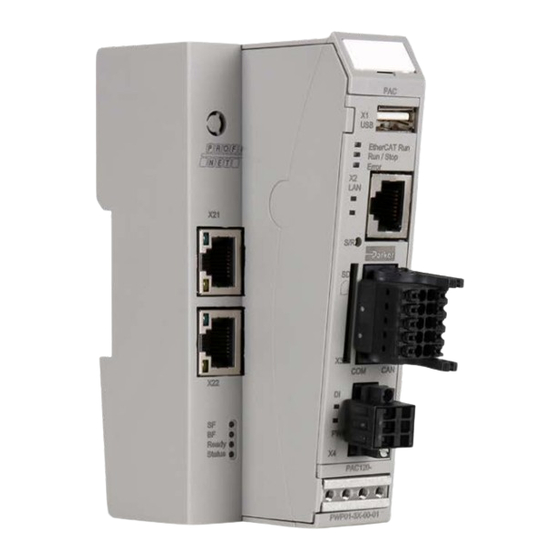
Page 8: Front View
Parker Automation Controller Parker Automation Controller Product Description Product Description Series PAC120 Series PAC120 4.4 Front View 4.5.1 Ethernet “LAN” The onboard 10/100 Mbit base-T Ethernet adapter attaches the unit to a network through its RJ-45 connector. LEDs "Link" and "Activity" tell you whether the unit is properly connected to the network. -
Page 9: Serial Communication Rs-232 / Can1
USB stick, you should always ensure that no program still has an open file loaded from the stick. 4.5.7 SD Card • Before pulling off the stick, always use the function USB_UMountDisk from the Parker System Library iMX6 PAC120 features a SD card slot at its front. The slot is marked with a SD icon. -
Page 10: Indicators And Controls
Parker Automation Controller Parker Automation Controller Hazards Product Description Series PAC120 Series PAC120 4.7 Indicators and Controls 4.7.1 Status LEDs LED LAN (link) The status LEDs indicate the state of the PAC120 modules. RUN/STOP is indicative of the soft PLC status. -
Page 11: Operation
Parker Automation Controller Parker Automation Controller Operation Operation Series PAC120 Series PAC120 5. Operation 5.1.2 Electrical Installation 5.1 Installation Earthing 5.1.1 Mechanical Installation Connect the PAC modules to earth by attaching the metal housing to functional earth. PAC120 / PACHC / PACIO modules are intended for mounting rail instal- Since the functional earth connector dissipates HF currents, it is of utmost importance for the module's noise im- à... -
Page 12: Configuration
Parker Automation Controller Parker Automation Controller Operation Operation Series PAC120 Series PAC120 5.2 Configuration 5.3 Web Interface A web interface is used to configure PAC120. After logging in, you can check and change various system settings 5.3.1 Web Interface – Login and/or display system information. -
Page 13: Menu - Configuration
Parker Automation Controller Parker Automation Controller Operation Operation Series PAC120 Series PAC120 5.3.2 Menü – Configuration 5.3.2.1 Menu Item “Network” Network mode: ethercat This mode defines the network interface as an EtherCAT device. We recommend using eth1 for EtherCAT. In CODE- Use this page to change various of the control unit's network settings. -
Page 14: Menu Item „Ssh Server
Parker Automation Controller Parker Automation Controller Operation Operation Series PAC120 Series PAC120 5.3.2.6 Menu Item „SSH-Server“ 5.3.2.8 Menu Item „Users“ Use this page to change the passwords of the users registered with the control unit. You may also create up to five custom "ftpusers", assign any user name and root directoy to them, enable or dis- able them and set their privileges based on the three default "ftpuser". -
Page 15: Menu - System
Parker Automation Controller Parker Automation Controller Operation Operation Series PAC120 Series PAC120 5.3.3 Menu – System 5.3.4 Menu – PLC-Manager 5.3.3.1 Menu Item „Info“ 5.3.4.1 Control This page displays all major details of the control unit. Use this page to control the CODESYS V3 applications hosted by the control unit. -
Page 16: Application Info
Parker Automation Controller Parker Automation Controller Operation Operation Series PAC120 Series PAC120 5.3.4.2 Application Info 5.3.5 Menü – Diagnostics This page displays details of the control unit applications. 5.3.5.1 PLC Log • Applicationname This page shows the log of CODESYS V3 Runtime. Log details include: Unique name of the application. -
Page 17: Storage
By default, DejaVu series fonts are installed. If you wish to use other fonts such as Windows fonts for your Web- it is available, the browser will provide it for download. Save this file and send it to Parker for analysis. -
Page 18: Development Environment Codesys V3.5
Library providing access to the system settings • Parker iMX6 Onboard IO Library A separate plug-in, the Device Repository, provides the local system and your projects with the device definition Library of functions of the on-board IO module management functions. -
Page 19: Using The Project Templates
Choose the programming language for the program module “PLC_PRG”. à 6.2.1 Using the Project Templates On the Parker website project templates for different applications are stored that can be used as starting point for an own program development. 6.3 Creating a new Project You can create a new PAC project off line with no access to the controller. -
Page 20: Connecting With A Pac
The LED Run/Stop flashes repeatedly. Subsequently confirm your selection with “OK”. Now append the PAC120 BusCoupler (Internal E-Bus) to the EtherCAT Master. The device is the starting point of appending all further Parker PACIO EtherCAT series modules, e.g. PAC DI16/DO16. Devices tree with EtherCAT On the tab page “Communication Settings”, the green dot at the device symbol indicates that the device was found... -
Page 21: Adding Pachc Or Pacio (Online)
Parker Automation Controller Parker Automation Controller CODESYS V3.5 CODESYS V3.5 Series PAC120 Series PAC120 6.3.4 Adding PACHC or PACIO (online) Connected EtherCAT components are recognized automatically by PAC120. To this, the PAC must be connected As soon as the list is completed, click on “Copy all devices to the project” and the PACIO will be displayed in à... -
Page 22: Adding Pachc Or Pacio (Offline)
Then click on the tab “EtherCAT I/O Mapping”. This will open the I/O mapping dialogue which contains a table à Select Parker Hannifin as vendor and choose the PACHC or PACIO Slave Modul which matches with the hard- à with all I/O points. -
Page 23: Downloading Projects
Parker Automation Controller Parker Automation Controller CODESYS V3.5 CODESYS V3.5 Series PAC120 Series PAC120 6.4 Downloading Projects 6.4.2 Downloading CODESYS Projects 6.4.1 Downloading the Configuration and Program To download the CODESYS project itself to PAC120, proceed as follows. For downloading the source file, select “Download Source Code” in CODESYS. -
Page 24: Uploading Projects
Object "Onboard IO" for using the digital input of PAC120 is automatically added to the device tree when you create a project in CODESYS. Double-clicking on the object displays the configuration screen. Check tab "Parker:Internal I/O Map" for the address of the digital input. This tab also lets you do or create the mapping. -
Page 25: Profinet Settings
Parker Automation Controller Parker Automation Controller CODESYS V3.5 CODESYS V3.5 Series PAC120 Series PAC120 6.7 ProfiNet settings The PAC120 has a flexible mapping and supports acyclic data communication. Suitable function blocks for the Example Siemens Tia portal are available, which will simplify communication with a S7 PLC. These files can be found on The following example shows an exemplary data exchange for the values of a connected PACHC controller module: the PAC120 webpage. - Page 26 Siemens PLC Manual). The receive data from the PAC120 must be assigned to the IN-variables of the function block according to the data In addition to that Parker provides the function block PAC120_Profinet_Asyncron_DB to send and receive param- type: eters in which all data conversions and error handling is implemented.
- Page 27 Cyclic communication Acyclic communication Before calling up the Parker function block, the configuration for the read parameters with the data block Asyn- chron_Read_DB is done. In this example Int16[1], Int32[1], Real32[1] and String[1] are configured for reading.
-
Page 28: Maintenance / Servicing
Parker Automation Controller Parker Automation Controller Maintenance / Service Technical Date Series PAC120 Series PAC120 7. Maintenance / Servicing 8. Ordering Code 7.1 General Only qualified persons may work on PAC120. CAUTION Elektro- Software Communication Extended Extended hydraulic visualization Profinet IRT... - Page 29 Parker Automation Controller Parker Automation Controller Technical Date Accessories Series PAC120 Series PAC120 Dimensions 10. Accessories Modul type Item number Description PACIO Bus coupler PACIO-400-00 PACIO EtherCAT bus coupler, 3 A PACIO-450-02 PACIO DI16/DO16 (16 inputs/8 outputs), 1 A PACIO-450-03 PACIO DI16/DO16 (16 inputs/16 outputs), 1 ms time delay, 0.5 A...
-
Page 30: Disposal
Parker Automation Controller Parker Automation Controller Index Index Series PAC120 Series PAC120 11. Index Description Page Description Page Description Page Description Page Accessories Fieldbus Technology Ordering Code Taking out of Service Adding PACHC or PACIO (offline) Firmware Update Technical Data... - Page 31 © 2020 Parker Hannifin Corporation. All rights reserved. MSG11-5715-719/UK, 04/2020 EMEA Product Information Centre Free phone: 00 800 27 27 5374 (from AT, BE, CH, CZ, DE, DK, EE, ES, FI, FR, IE, IL, IS, IT, LU, MT, NL, NO, PL, PT, RU, SE, SK, UK, ZA)
Need help?
Do you have a question about the PAC120 Series and is the answer not in the manual?
Questions and answers