Table of Contents
Advertisement
Quick Links
COMPAX-M / COMPAX-S - Option F2
C O M P A X f i e l d b u s i n t e r f a c e
I n t e r b u s - S
W e a u t o m a t e m o t i o n
Subject to technical modification. Data based on the technical prior art at the time of printing.
from COMPAX software version >V5.0
from Interbus-S – Software version >V2.1
Main Office
Parker Hannifin GmbH
DIN EN ISO 9001
EMD HAUSER
P. O. Box: 77607-1720
Robert-Bosch-Str. 22
D-77656 Offenburg, Germany
Phone: +49 (0)781 509-0
Fax:
http://www.Parker-EMD.com
Great Britain:
Parker Hannifin plc
EMD Digiplan
21 Balena Close
Poole, Dorset
BH17 7DX UK
Phone: +44 (0)1202 69 9000
+49 (0)781 509-176
Fax:
http://www.Parker-EMD.com
14.01.00 12:56
192-040020 N4
January 2000
+44 (0)1202 69 5750
Advertisement
Table of Contents

Related Manuals for Parker Hauser COMPAX-M Series


Summary of Contents for Parker Hauser COMPAX-M Series
- Page 1 I n t e r b u s - S from COMPAX software version >V5.0 from Interbus-S – Software version >V2.1 January 2000 Main Office Great Britain: Parker Hannifin GmbH Parker Hannifin plc DIN EN ISO 9001 EMD HAUSER EMD Digiplan P. O. Box: 77607-1720...
-
Page 2: Table Of Contents
COMPAX - Option F2: Interbus-S Contents 2.7.2 POSR........... 33 Introduction............4 2.7.3 LAGE_ZIEL.......... 33 2.7.4 S1............34 Addressing ............4 2.7.5 LAGE_IST..........35 2.7.6 S2............35 Bus connection ..........4 2.7.7 S12............35 1.2.1 The bus wiring ........4 2.7.8 REALNULL .......... 36 2.7.9 GRENZEN.......... - Page 3 2.12.9 PED_INI..........75 Device allocation 2.12.10 PAD_INI..........76 2.12.3 IN_SELECT ......... 77 2.12.4 OUT_SELECT ........77 This documentation applies for these devices: 2.12.5 OUT_ENABLE ........78 ♦ COMPAX 10XXSL with the Option F2 (available 04/2000) ♦ COMPAX 25XXS with the Option F2 DRIVECOM-PROFILE 22, from COMPAX ♦...
-
Page 4: Introduction
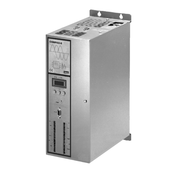
Interbus-S 1. Introduction 1. Introduction The communication module Option F2 (IFM9) allows 1.2.1 The bus wiring COMPAX-M/S to contact the Interbus-S by the company Phoenix. The Interbus-S protocol is based on a summation- frame message and is optimised for the cyclical and time NM D COMPAX-M with option F2 equi-distant transmission of process data. -
Page 5: Pdu Length
PDU Length 1.2.1 The bus wiring Connections SSK13/ : 1.3 Identification code (ID- The assignment on the network module or on the Code) COMPAX-S corresponds to the Interbus-S - standard. Possible connections with SSK13/..: → Network module X6 (IN) Network module X7 (OUT) →... -
Page 6: Selectable Data Channels
Interbus-S 1. Introduction 1.4 Selectable Data Channels The length of the process data depends on the Interbus-S software version and the COMPAX Parameter P196 (see also page 81). The described features are not only valid for the process output data (PAD: data for COMPAX) but also for the process input data (PED: data from COMPAX Master ⇒... - Page 7 Selectable Data Channels 1.2.1 The bus wiring If you assign OBJECT_REQ to PAD and OBJECT_RSP to PED Overview you will have access to all objects with a data length ≤ 4 bytes. P196 Bit 0...2 = "4": 8 byte process data channel In addition to this fixed PD assignment, a new function which allows temporary assignment of the PD was created as a further P196 Bit 7="0": PD1/PD2: STEUERWORT/STATUSWORT...
-
Page 8: Bus - Setting Using The
Interbus-S 1. Introduction 1.4.1 Bus – Setting using the front cover The bus protocol (P196) can be set using the COMPAX front cover. Procedure: choice of operation modes Enter Enter call smaller call higher call higher call smaller Status Status C-parameter C-parameter number... -
Page 9: Data Types
Data types 1.7.1 Boolean 1.7.3 Unsigned 1.7 Data types Unsigned values are unsigned quantities. Physically, the types consist of one or more octets (Bytes). One byte consists of 8 bits (Bit 0 to 7). Bit 0 is the LSB Type Value range Length (Least Significant Bit). -
Page 10: Object Index
Interbus-S 2. Object index 2. Object index 2.1 Communication objects: Overview sorted by Symbol Index Sub- Command Symbol Index Byte Service page pointer index Deceleration time ACCEL_NEG 0x5feb Acceleration time ACCEL_POS 0x5fea Operation mode display BETR_ART_AZ 0x6061 Operation mode selection code BETRIEBSART rd/wr 0x6060 Special commands for COMPAX XX70... - Page 11 Communication objects: Overview sorted by Symbol Index Sub- Command Symbol Index Byte Service page pointer index RAMPE_NEG rd/wr 0x6084 Rapid stop RAMPE_NOTS rd/wr 0x6085 Acceleration RAMPE_POS rd/wr 0x6083 Accelerate reference run RAMPE_REF rd/wr 0x609a Ramp form speed RAMPENFORM rd/wr 0x6086 Reference measurement offset REALNULL rd/wr 0x607c...
-
Page 12: Index
Interbus-S 2. Object index 2.2 Communication objects: Overview sorted by Index Command Symbol Service Index Index Sub- Byte Index index page Write/read objects via process data channel OBJECT_REQ 0x5fc5 Write/read acknowledgement/ answer obj. via PDK OBJECT_RSP 0x5fc6 Speed step profile with ACCEL PRXSDYALZ 0x5fc7 Set and read curve memory pointer... - Page 13 Command Symbol Service Index Index Sub- Byte Index index page Enable process output data OUT_ENABLE rd/wr 0x5fff PE data description PE_SELECT rd/wr 0x6000 0...13 PA data description PA_SELECT rd/wr 0x6001 0...13 Enable PA data PA_ENABLE rd/wr 0x6002 Function group description FKT_GRUPPE 0x600f 1...7...
-
Page 14: Device Identification
Interbus-S 2. Object index 2.3 Device identification 2.3.1 FKT_GRUPPE Function group description This parameter displays the function groups from which functions are integrated in the device. The parameter is a field with 4*n entries. Each entry consists of the profile group, the profile version, the function group identifier and the function version. Object Description Index 0x600f... -
Page 15: S31_S39
Device identification 2.3.2 S31_S39 2.3.2 S31_S39 Device identification. Object Description Index 0x5fd6 Symbol Length Access groups S31-S39 Object code Elements Password Array Data type Access rights PD Map Octet string Read all Not possible Data Description Coding Value range 000000000000 ... 999999999999 Data byte [Bit] Assignment Data byte [Bit]... -
Page 16: Control
Interbus-S 2. Object index 2.4 Control 2.4.1 Operating mode Operation mode selection code. Selection function that determines the operation mode. Object Description Index 0x6060 Symbol Length Access groups BETRIEBSART Object code Password Simple var. Data type Access rights PD Map Integer16 Read/write all Not possible... -
Page 17: Steuerbyte
Control 2.4.3 STEUERBYTE 2.4.3 STEUERBYTE Allows program start from record 1 - 15. The record pointer is set to the corresponding program record. The program can be started, stopped, and continued. " The machine zero is approached with the record selection = "0000" and "Start". An error acknowledgement is possible. -
Page 18: Cpx_Stw
Interbus-S 2. Object index 2.4.5 CPX_STW Activation of device control commands and setting/resetting of virtual inputs E17...E32 Control of the COMPAX M/S via the CPX control word is only possible when the relevant bits in P221 are set. The virtual inputs E17...E32 can be queried in the data memory. Object Description Index 0x5FD2... -
Page 19: Cpx_Zsw
Control 2.4.6 CPX_ZSW Example: Switch from Hand+ to Hand- Reset Hand+: data bit 1[0] = "0" Wait until COMPAX has recognised through the Interbus-S (till "Ready to start" has been set) or Handshake through CPX_STW. Set Hand-: data bit 1[1] = "1" 2.4.6 CPX_ZSW The CPX status word shows information about the status of the device as well as messages. -
Page 20: Steuerwort
Interbus-S 2. Object index 2.4.7 STEUERWORT Some bits in the control word influence the status equipment of the device control, enabling functions and determining the operating status of the devices. The manufacturer-specific bits (Data byte 1 bits 2...6) serve to activate devices control commands, which are only effective if P221 is used to provide the appropriate enabling (see CPX_STW). -
Page 21: Pop-Up Message Processing
Control 2.4.9 Pop-up message processing 2.4.9 Pop-up message processing COMPAX can display the following pop-up messages via the status word: % an error has occurred. % the programmed set point has been reached. % the programmed comparator point has been reached. The pop-up messages can be enabled individually via P193 (activated). -
Page 22: Control
Interbus-S 2. Object index 2.4.10 CONTROL Control commands. Compax commands which do not require additional values. The required commands are activated by reading in the relevant command number. Object Description Index 0x5fe9 Symbol Length Access groups CONTROL Object code Password Simple var. -
Page 23: Command
Control 2.4.11 COMMAND 2.4.11 COMMAND All COMPAX commands which exist for the RS232 interface can be transferred with this object in plain text (ASCII-String in upper case letters). Object Description Index 0x5fe6 Symbol Length Access groups COMMAND Object code Password Simple var. - Page 24 Interbus-S 2. Object index 2.4.13 Read/write COMPAX parameters in binary format. The corresponding parameter is selected using the Sub-index (Sub-index = parameter No.). Object Description Index 0x5fd4 Symbol Length Access groups Object code Elements Password Array Data type Access rights PD Map Integer32 Read/write all...
-
Page 25: Diagnosis
Diagnosis 2.5.1 STOERUNG 2.5 Diagnosis 2.5.1 STOERUNG Fault code. If COMPAX is in the "Fault" status, the fault code is given a value not equal to 0. If COMPAX is not in the "Fault" status, this object then gives the value 0. Object Description Index 0x603f... -
Page 26: S30
Interbus-S 2. Object index 2.5.2 S30 Error message. This object contains the error number of the current error and the last occurring error. If the error number of the current error = 0, there is no error. Object Description Index 0x5fd7 Symbol Length... -
Page 27: S11
Diagnosis 2.5.5 2.5.5 S9 Number of axis motion cycles. Object Description Index 0x5fdc Symbol Length Access groups Object code Password Simple var. Data type Access rights PD Map Unsigned32 read all not possible 2.5.6 S11 Loop counter for a running REPEAT loop. Object Description Index 0x5fda... - Page 28 Interbus-S 2. Object index 2.5.8 S All Compax status values that exist for the RS232 interface can be read with this object. The response is made available in plain text (as ASCII string). The corresponding status is selected using the Sub-index (Sub-index = status No.). Object Description Index 0x5fe8...
-
Page 29: Torque, Current, Voltage
Torque, current, voltage 2.6.1 MOMENT_MAX 2.6 Torque, current, voltage 2.6.1 MOMENT_MAX Max. torque value. This value is the maximum permissible torque for the motor. Object Description Index 0x6072 Symbol Length Access groups MOMENT_MAX Object code Password Simple var. Data type Access rights PD Map Unsigned16... -
Page 30: Moment_Ist
Interbus-S 2. Object index 2.6.3 MOMENT_IST Torque actual value. The torque actual value corresponds to the current torque in the drive motor. Object Description Index 0x6077 Symbol Length Access groups MOMENT_IST Object code Password Simple var. Data type Access rights PD Map Integer16 Read all... -
Page 31: Zwk_Spg
Torque, current, voltage 2.6.6 ZWK_SPG 2.6.6 ZWK_SPG Intermediate circuit voltage. This parameter describes the current intermediate circuit voltage in the drive controller. Object Description Index 0x6079 Symbol Length Access groups ZWK_SPG Object code Password Simple var. Data type Access rights PD Map Unsigned16 read all... -
Page 32: Positioning
Interbus-S 2. Object index 2.7 Positioning 2.7.1 POSA Absolute positioning. Reference point is real zero (RN). Positioning is done with the acceleration time (brake time) set by ACCELL-POS (ACCEL-NEG) and the velocity set by SPEED. If these values were not set, then valid are substitute values: SPEED: Parameter P002; ACCEL: Parameter P006 Object Description Index 0x5ff0... -
Page 33: Posr
Positioning 2.7.2 POSR 2.7.2 POSR Relative positioning. Reference point is the current position. Object Description Index 0x5fef Symbol Length Access groups POSR Object code Password Simple var. Data type Access rights PD Map Octet String Write all Not possible Data Description Data format Unit mm (or inch) - Page 34 Interbus-S 2. Object index Function: Transition Meaning Conditions New set point New target value Target val.- acknowledgement. ="0" actual value can be transferred Set point Set point acknow- Set point acknowledgement ="1" Set point acknowledgement ledgement recognised New set point New set point ="0"...
-
Page 35: Lage_Ist
Positioning 2.7.5 LAGE_IST 2.7.5 LAGE_IST Position actual value. Current drive position. Object Description Index 0x6064 Symbol Length Access groups LAGE_IST Object code Password Simple var. Data type Access rights PD Map Integer32 Read all Data Description 1 ⇔ 0.001 mm (or inch) Unit Resolution mm (or inch) -
Page 36: Realnull
Interbus-S 2. Object index 2.7.8 REALNULL Reference measurement offset. Difference between real null point and machine zero point. After the reference run, all positioning processes refer to the real null point. Object Description Index 0x607c Symbol Length Access groups REALNULL Object code Password Simple var. -
Page 37: Pos_Fenster
Positioning 2.7.10 POS_FENSTER 2.7.10 POS_FENSTER Positioning window. The positioning window lies symmetrically around the target position. Once the position actual value lies within this window, the Bit "Position reached" is set in the status word. Object Description Index 6067 Symbol Length Access groups POS_FENSTER... -
Page 38: Polaritaet
Interbus-S 2. Object index 2.7.12 Contour error. Difference between set and actual position in a positioning cycle. Object Description Index 0x5ffa Symbol Length Access groups Object code Password Simple var. Data type Access rights PD Map Integer16 read all Data Description Unit Resolution mm (or inch) -
Page 39: Cam_Cmd
Positioning 2.7.15 CAM_CMD Data Description Selection code Method Selection code Method MN-Ini. approach in direction 1 MN-Ini. approach in direction 2 The COMPAX parameter P213 is influenced by this object. The direction in which the machine zero is approached is also influenced by the COMPAX parameters P212 (machine zero mode) and P3 (speed of machine zero travel). -
Page 40: Waitposr
Interbus-S 2. Object index Example A cutting length of 205.000 mm is required. Service Sub-index 3. data byte Write request 0x20 Command Code Length 4. data byte 0x8082 0xc8 Param. counter 1. data byte 0x00 Index 2. data byte 0x5fe0 0x03 2.7.17 WAITPOSR... -
Page 41: Speed
SPEED 2.8.1 SPEED 2.8 SPEED 2.8.1 SPEED Traverse speed in % of the nominal speed (nominal rpm * travel per motor revolution). The value is valid until a new value is programmed. The set speed can be reduced by using the OVERRIDE object. A speed change during the positioning cycle is possible by using the POSR0SPEED object. -
Page 42: Posr0Speed
Interbus-S 2. Object index 2.8.3 POSR0SPEED Changing traverse speed during a positioning cycle. Object Description Index 0x5fed Symbol Length Access groups POSR0SPEED Object code Password Simple var. Data type Access rights PD Map Octet String Write all Not possible Data Description Data format Unit 1 ⇔... -
Page 43: Prxsdyalz
SPEED 2.8.5 PRXSDYALZ Example The drive should continue travel at 33% of the nominal speed after 580 mm. Service Length 5. data byte Write request 0x00 Command Code 1. data byte 6. data byte 0x8082 0x00 0x00 Param. counter 2. data byte 7. -
Page 44: Drehzahlmax
Interbus-S 2. Object index 2.8.6 DREHZAHLMAX Maximum motor speed value. The maximum speed is given for both directions of rotation with a resolution of 1 rpm. These are for the protection of the motor and can be found in the motor data sheet. Object Description Index 0x6080... -
Page 45: Verf_Geschw
SPEED 2.8.8 VERF_GESCHW 2.8.8 VERF_GESCHW Traverse speed. Given in % of the nominal speed (nominal rpm * travel per motor revolution). The value is valid until a new value is programmed. The set speed can be reduced by using the OVERRIDE object. A speed change during the positioning cycle is possible by using the POSR0SPEED object. -
Page 46: Geschw_Ist
Interbus-S 2. Object index 2.8.10 GESCHW_IST Traverse speed - actual value. Value in % of the nominal speed (nominal rpm * travel per motor revolution). Object Description Index 0x606c Symbol Length Access groups GESCHW_IST Object code Password Simple var. Data type Access rights PD Map Integer32... -
Page 47: Acceleration
Acceleration 2.9.1 RAMPENFORM 2.9 Acceleration 2.9.1 RAMPENFORM Ramp form speed. Selection function with which the acceleration process is written. Object Description Index 0x6086 Symbol RAMPENFORM Length Access groups Object code Password Simple var. Data type Access rights PD Map Integer16 Read/write all Not possible Data Description... -
Page 48: Accel_Neg
Interbus-S 2. Object index 2.9.3 ACCEL_NEG Deceleration time. Time setting for the deceleration process. SPEED • ACCEL_NEG The time specification applies to nominal speed (100%). 100% Object Description Index 0x5feb Symbol Length Access groups ACCEL_NEG Object code Password Simple var. Data type Access rights PD Map... -
Page 49: Rampe_Neg
Acceleration 2.9.5 RAMPE_NEG 2.9.5 RAMPE_NEG Lag. Time setting for the deceleration process. SPEED • RAMPE_NEG The time specification applies to nominal speed (100%). 100% Object Description Index 0x6084 Symbol Length Access groups RAMPE_NEG Object code Password Simple var. Data type Access rights PD Map Unsigned32... -
Page 50: Rampe_Ref
Interbus-S 2. Object index 2.9.7 RAMPE_REF Reference run acceleration. Acceleration time for approaching the machine zero point. SPEED • RAMPE_REF The time specification applies to nominal speed (100%). 100% Object Description Index 0x609a Symbol Length Access groups RAMPE_REF Object code Password Simple var. -
Page 51: Inputs/Outputs
2.10 Inputs/outputs 2.10.1 INPUT_WORD 2.10 Inputs/outputs 2.10.1 INPUT_WORD Logic state of the 16 digital inputs. Some inputs are assigned fixed control functions. Input Assignment Input Assignment SHIFT 1 & 3 Find real null (RN) Hand+ 1 & 4 Teach real zero Hand- 1 &... -
Page 52: Output
Interbus-S 2. Object index 2.10.3 OUTPUT Set or reset a digital output. The corresponding output is selected using the Sub-index (Sub-index = output no.). Some outputs have a fixed status information assigned (see OUTPUT-WORD). Object Description Index 0x5ff6 Symbol Length Access groups OUTPUT Object code... -
Page 53: Posroutputp
2.10 Inputs/outputs 2.10.5 POSROUTPUTP 2.10.5 POSROUTPUTP Comparator function (active high). Set an unassigned output within a positioning cycle. The position value is given as a relative measurement. It is referenced to the positioning start point. A maximum of 8 comparators can be set for a positioning process. The corresponding output is selected using the Sub-index (Sub-index = output no.). -
Page 54: Programming
Interbus-S 2. Object index 2.11 Programming 2.11.1 Reading and writing the program memory with command records in plain text (ASCII format). The record number is determined with the sub-index (Sub-index = record No.) Object Description Index 0x5ff1 Symbol Length Access groups Object code Elements Password... - Page 55 2.11 Programming 2.11.2 COMPAX – Command codes Definition of the command code A command code consists of 1 byte. Sorted by command code Sorted by command code Code Command Code Command 0x20 0x6C ACCEL Parameter Empty instruction (No Operation) 0x01 VALIDP / C / F 0xCC ACCEL Variable...
- Page 56 Interbus-S 2. Object index Operand codes An operand consists of 7 bytes; 1 byte for the type indicator and 6 data bytes. Operand Type Parameter 0x50 No.H Nr.L 0x00 0x00 0x00 0x00 Status 0x53 No.H Nr.L 0x00 0x00 0x00 0x00 Variable 0x56 No.H...
- Page 57 2.11 Programming 2.11.2 COMPAX Set memory-command code table Command Code ACCEL Parameter 0x6C No.H Nr.L ACCEL Variable 0xCC No.H Nr.L ACCEL Value 0x4C 0x45 0x00 GOSUB EXT 0x42 0x00 0x00 GOSUB Value 0x42 GOTO EXT 0x47 0x00 0x00 GOTO Value 0x47 IF ERROR GOSUB n 0x49...
- Page 58 Interbus-S 2. Object index Command Code SPEED Value 0x53 SPEED SYNC 0x53 0xFF 0xFF 0xFF 0xFF 0xFF 0xFF VALIDP 0x01 0x56 0x50 VALIDC 0x01 0x56 0x43 VALIDF 0x01 0x56 0x46 WAIT Parameter 0x77 No.H Nr.L WAIT Variable 0x7D No.H Nr.L WAIT Value 0x57 WAIT START...
- Page 59 2.11 Programming 2.11.2 Command Code Vn=<Operand1> [ <Arithmetic Operator> <Operand2> ] 0x56 n MSB n LSB O1D1 O1D2 O1D3 O1D4 O1Type O1D5 O1D6 AriOp O2D1 O2D2 O2D3 O2D4 O2Type O2D5 O2D6 Key: No.H: High byte of the parameter/variable number Nr.L: Low byte of the parameter/variable number MSB: High byte of an integer value...
-
Page 60: Goto
Interbus-S 2. Object index 2.11.3 GOTO Set and read record pointer. Object Description Index 0x5ff2 Symbol Length Access groups GOTO Object code Password Simple var. Data type Access rights PD Map Unsigned8 Read/write all Not possible Data Description Data format Unit Binary Record number... -
Page 61: Start_N_Go
2.11 Programming 2.11.5 START_N_GO 2.11.5 START_N_GO Start program at record N. The record pointer is set to the corresponding program record and then the program is started. Object Description Index 0x5fe5 Symbol Length Access groups START_N_GO Object code Password Simple var. Data type Access rights PD Map... -
Page 62: Cam_Mem_P
Interbus-S 2. Object index 2.11.7 CAM_MEM_P Special command for COMPAX XX70. Set and read curve memory pointer. Object Description Index 0x5fca Symbol Length Access groups CAM_MEM_P Object code Password Simple var. Data type Access rights PD Map Unsigned16 Read/write all Not possible Data Description Data format... - Page 63 2.11 Programming 2.11.9 Data description (P196 Bit 4 = "0") Variable Resolution Variable Resolution 1 ⇔ 0.001 001 .. 005 023 .. 029 1 ⇔ 0.001 006 .. 010 030 .. 034 1 ⇔ 0.001 1 ⇔ 0.000001 011 .. 016 035 ..
-
Page 64: Object_Req And Object_Rsp For 8 Byte Process Data Channel
Interbus-S 2. Object index OBJECT_REQ and OBJECT_RSP for 8 byte process data channel The two new objects OBJECT_REQ and OBJECT_RSP make it possible to access all communication objects (or certain elements) with a data width of ≤ 4 byte via the process data channel. The object OBJECT_REQ can be assigned to the PAD channel (PAD3...PAD8): ♦... - Page 65 OBJECT_REQ and OBJECT_RSP for 8 byte process data channel 2.11.9 OBJECT_REQ, OBJECT_RSP Example: P196 Bit 0..2 = "4" (8 Byte process data), P196 Bit 7 ="0" (PD1/2 = STEUERWORT / STATUSWORT), P196 Bit 5 = "1" (OBJECT_REQ and OBJECT_RSP can be temporarily assigned to PD), P196 Bit 6 = "0"...
-
Page 66: Object_Req
Interbus-S 2. Object index OBJECT_REQ Write or read communication via process data channel. The object is selected with the 7 Bit-wide index pointer (please see footnote); the respective element of an object is selected with the sub-index. The highest bit of the data byte 1 determines the object access (0 = write; 1 = read). The acknowledgement for a write-access or the answer for a read-access is passed onto the object OBJECT_RSP. -
Page 67: Process Data Control
2.12 Process data control 2.12.1 PAD_Steuerung 2.12 Process data control This function emulates the process data, which are transmitted via the process data channel, on the communication objects. The COMPAX process data channel has a width of 2, 4 or 6 bytes; depending on the value in parameter 196. Each byte can be read and written by COMPAX. - Page 68 Interbus-S 2. Object index Setting the PAD: using the object "Process Output Data Description" (PA_SELECT; see page 73), using the COMPAX parameters P139, P140, P141, P142 (corresponds to the object PAD_INI; see page 76). You may place each of the named objects on the PAD channel according to its required bytes. Set the corresponding COMPAX parameter to the value given for the respective object (see table above).
- Page 69 2.12 Process data control 2.12.1 PAD_Steuerung Example assignments for the PAD's The POSITION_TARGET and SPEED objects are represented on the PAD's. PAD1(3) PAD2(4) PAD3(5) PAD4(6) PAD5(7) PAD6(8) "1" "0" "1" "0" "1" "0" "1" "0" "1" "0" "1" "0" Bit0 Bit1 Bit2 Bit3...
-
Page 70: Ped_Steuerung
Interbus-S 2. Object index 2.12.2 PED_Steuerung The process input data can be used to cyclically read from the following COMPAX communication objects. Object name Description Index Byte COMPAX - Parameter Number page P135 ... P138 STATUSBYTE Status byte 24527 0x5fcf STATUSWORT Status word 24641... - Page 71 2.12 Process data control 2.12.2 PED_Steuerung The COMPAX parameters P135, P136, P137 and P138 initiate the object PI_SELECT and thereby the PED channel after the COMPAX is turned on. These parameters can be read and written to using the PED_INI object. PE_SELECT allows the channels to be freely assigned.
-
Page 72: Pe_Select
Interbus-S 2. Object index 2.12.6 PE_SELECT Process Input Data - Description. This parameter contains the data that define which process input data are emulated on which communication objects. Communication objects which can be emulated on PED data are designated in the respective object descriptions. Object Description Index 0x6000... -
Page 73: Pa_Select
2.12 Process data control 2.12.7 PA_SELECT 2.12.7 PA_SELECT Process Output Data - Description. This parameter contains the data that define which process output data are emulated on which communication objects. Communication objects which can be emulated on PA data are designated in the respective object descriptions. Object Description Index 0x6001... -
Page 74: Pa_Enable
Interbus-S 2. Object index 2.12.8 PA_ENABLE Enable process output data. Each bit of this parameter is associated with a byte of the process output data channel. Meaning: Bit = 0 the corresponding process data value is disabled Bit = 1 the corresponding process data value is enabled If an object takes up several bytes on the PA data channel, the logic state of the bit which is associated with the first byte of this object is the one used, and the other associated bits are not relevant. -
Page 75: Ped_Ini
2.12 Process data control 2.12.9 PED_INI 2.12.9 PED_INI Initialising the process input data description. This object contains the data that define which process input data are emulated on which communication objects after COMPAX is switched on. Communication objects which can be emulated on PED data are designated in the respective object descriptions. Object Description Index 0x5fd0... -
Page 76: Pad_Ini
Interbus-S 2. Object index 2.12.10 PAD_INI Initialising the Process Output Data - Description. This object contains the data that define which process output data are emulated on which communication objects after COMPAX is switched on. Communication objects which can be emulated on PA data are designated in the respective object descriptions. Object Description Index 0x5fd1... -
Page 77: In_Select
2.12 Process data control 2.12.3 IN_SELECT 2.12.3 IN_SELECT Process Input Data - Description. This object defines, which communication object or communication object element will be depicted on the 1 byte (and if applicable, the subsequent bytes) process input data of the process data channel.. Object Description Index 0x5ffd... -
Page 78: Out_Enable
Interbus-S 2.12.5 OUT_ENABLE Enable process output data. This parameter is allocated to the 1 byte of the process output data channel. Meaning: "OUT_ENABLE" = FALSE the corresponding process data value is disabled "OUT_ENABLE" = TRUE the corresponding process data value is enabled Object Description Index 0x5fff... - Page 79 3 . D R I V E C O M - P R O F I L E 2 2 , f r o m C O M P A X S o f t w a r e - V e r s i o n 3 . 0 1 From program version V3.01onwards, the operating type 'DRIVECOM-PROFIL' is available in all COMPAX variants.
-
Page 80: Drivecom-Profile 22, From Compax Software-Version 3.01
Interbus-S 3. DRIVECOM-PROFILE 22, from COMPAX Software-Version 3.01 Status Description NICHT-EINSCHALTBEREIT: Self-test is running Initialisation is running Drive function is disabled All functions are disabled EINSCHALTSPERRE: Software/hardware initialisation is terminated Communication via all interfaces is enabled Modifications to parameters, variables, records is possible Drive function is disabled (motor dead) Display shows 'OFF' EINSCHALTBEREIT:... -
Page 81: Compax Parameters For The Interbus-S
4. COMPAX Parameters for the Interbus-S Meaning Minimum Default Maximum When value value value valid P190 ="0": DRIVECOM profile defined turn on procedure inactive Set operating type "DRIVECOM profile Power on ="22": DRIVECOM profile defined turn on procedure active 22" P191 Bus time-out ="0": no response, except error message E73, during a time-out... -
Page 82: Compax Interbus-S Error Messages
Interbus-S 5. COMPAX Interbus-S Error messages 5. COMPAX Interbus-S Error messages Cause Remedy / Causes Acknowl edge power to with drive E73 Time-out error Re-send the characters nein The error response is influenced with P191. No acknowledgement necessary; the error message is cancelled after the next errorless transmission. Depends on P191. -
Page 83: Index
6 . I n d e x 8 byte process data channel....65 IN_SELECT ........78 Power or intermediate circuit 8 Byte Process data channel ....6 Index-pointer........10 voltage ..........32 Absolute positioning ......33 INPUT_WORD........52 Process data control ......68 Absolute value sensor .......36 Inputs/outputs ........ - Page 84 Interbus-S 6. Index...
Need help?
Do you have a question about the Hauser COMPAX-M Series and is the answer not in the manual?
Questions and answers