
Related Manuals for Parker Porter MPC Series


Summary of Contents for Parker Porter MPC Series
- Page 1 MPC SERIES PANEL MOUNT MASS FLOW CONTROLLER “INSTALLATION & PROGRAMMING” USER’S MANUAL FM-1038 Rev. 0 4/08...
-
Page 2: Table Of Contents
TABLE OF CONTENTS SAFETY PRECAUTIONS .........................1 Section 1 – INTRODUCTION......................2 Preface ........................2 Features ........................2 Functions ........................3 Model Selection Guide ....................4 Section 2 – PRODUCT SPECIFICATIONS ..................5 Section 3 – DISPLAY TERMS AND FUNCTIONS................7 Display (Front View) ....................7 Definition of Terms .................... -
Page 3: Safety Precautions
SAFETY PRECAUTIONS WARNING Warnings are indicated when mishandling this product might result in death or serious injury to the user. CAUTION Cautions are indicated when mishandling this product might result in minor injury to the user or only physical damage to this product. WARNING Never allow gases within explosive limits to pass through the MPC Series Panel Mount Mass Flow Controller (MFC). -
Page 4: Section 1 - Introduction
SECTION 1 – INTRODUCTION PREFACE Thank you for purchasing Porter’s MPC Series Panel Mount Mass Flow Controller (MFC). Please keep this user’s manual available for future reference. Before operating the MPC Series Panel Mount MFC, please note the safety precautions (warnings and cautions). It is recommended these instructions be read and understood before performing any operation. -
Page 5: Functions
FUNCTIONS MULTI-SETTING FUNCTION Up to four (4) preset flow rate settings can be instantaneously switched to by key operation or external switching input. GAS TYPE SWITCHING FUNCTION The gas type to be used can be selected from the standard compatible gases by key operation. GAS TYPE SETTING FUNCTION The user can set conversion factors for any gas type, including mixed gases, to accommodate gases other than standard compatible gases. -
Page 6: Model Selection Guide
The operating mode can be identified and output externally as an event. The output ON delay time can also be programmed. However, the delay cannot be set to totalization pulse output. In addition, the output logic can be reversed (during normal operation: ON;... -
Page 7: Section 2 - Product Specifications
SECTION 2 – PRODUCT SPECIFICATIONS Model Number MPC95 MPC02 MPC05 MPC20 Control Valve Type Normally closed proportional solenoid valve Maximum Flow Capacity (N unless otherwise 0.5 SLPM 2.0 SLPM (N or Helium) 5.0 SLPM 20 SLPM noted) (Note 1) Nitrogen/air, oxygen, argon, carbon dioxide (all models except Model MPC02-BBNHP1); Compatible Gases Helium (Model MPC02-BBNHP1 only) - Gas must be dry, clean and oil-free. - Page 8 PRODUCT SPECIFICATIONS (continued) External Number of Inputs Contact Input Input Type Potential-free contact or open collector Contact OFF Terminal Voltage 2.0 Vdc (±0.5Vdc) Contact ON Terminal Current Approx. 0.5 mAdc (contact current) Allowable ON Contact Resistance 250 ohms maximum Allowable OFF Contact 100k ohms minimum Resistance Allowable ON Residual Voltage...
-
Page 9: Section 3 - Display Terms And Functions
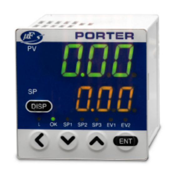
SECTION 3 – DISPLAY TERMS AND FUNCTIONS DISPLAY (FRONT VIEW) DEFINITION OF TERMS SP (Setpoint): Set flow rate value. PV (Process Variable): Instantaneous flow rate value (i.e. controlled flow rate). Operation mode: Three (3) modes of ‘Valve Fully Closed’/’Valve Control’/’Valve Fully Open’. FUNCTIONS UPPER DISPLAY Displays the instantaneous flow rate value (7-segment display). -
Page 10: Rear View
REAR VIEW LOADER JACK: The connection of a dedicated loader cable (available separately) to the loader jack on the rear of the MFC enables direct communication with a personal computer. 1/8” FNPT inlet connector. ‘IN’ CONNECTOR: ‘OUT’ CONNECTOR: 1/8” FNPT outlet connector. - 8 -... -
Page 11: Section 4 - Mounting And Wiring
SECTION 4 – MOUNTING AND WIRING LOCATION Avoid mounting the MPC Series Panel Mount MFC in locations subject to: High and low temperature and humidity. Sudden changes in temperature and condensation. Corrosive and/or flammable gas-containing environments. Environments containing high amounts of dirt, dust, salt, conductive substances (e.g. metal particles, water, oil mist, etc.) and organic solvents. - Page 12 PANEL MOUNTING To panel-mount the MPC Series Panel Mount MFC, the panel thickness must be 2 to 9 mm (.079 to .35”) and a panel cut-out be made to accommodate the MFC’s 44.8 x 44.8 mm (1.764 x 1.764”) housing. To panel-mount multiple MFC’s, refer to the panel cutout dimensions below. Remove the mounting bracket from the MFC’s housing.
-
Page 13: External Electrical Connections
TUBING CONNECTION When the MPC Series Panel Mount MFC is panel-mounted, use tubing that does not stress the MFC housing. If metal piping is directly connected to the 1/8” FNPT connector of the MFC, the MFC should not be panel-mounted. Connect the tubing to ensure the gas flows in the direction from ‘IN’... - Page 14 WIRING TYPICAL WIRING - 12 -...
-
Page 15: Section 5 - Basic Operation
SECTION 5 – BASIC OPERATION SWITCHING DISPLAYS Each press of the [DISP] key switches the display as shown in the example below. Power ON Instantaneous Multi-setting flow rate indication flow rate indication *4, *5 Press [DISP] key (1 second or longer) Setting flow rate Instantaneous No. - Page 16 INSTANTANEOUS FLOW RATE DISPLAY (SETTING FLOW RATE DISPLAY) When power is turned ON, the instantaneous flow rate value is indicated on the upper display and the setting flow rate value is indicated on the lower display. Please note the number of effective digits displayed differs according to the MFC’s maximum flow.
-
Page 17: Setting The Flow Rate
SETTING THE FLOW RATE PROCEDURE FOR CHANGING FLOW RATE IN DIGITAL SETTING Single SP (Setpoint) Setting Mode (Single Setpoint Per Function Setup ‘C-04’) Follow the procedure below to change the SP (setpoint) value (set flow rate): Press the [DISP] key (the instantaneous flow rate and SP values are displayed [display at power supply ON]). - Page 18 switching the display. This function is useful when performing incremental changes to the SP value. As shown in the following table, up to four (4) SP values can be switched according to the ON/OFF status of the external switch inputs when the ‘3: Switching of SP No.’ is selected at the external switch input function assignments ‘C-10’...
-
Page 19: Selecting The Operation Mode
SELECTING THE OPERATION MODE When the [DISP] key is pressed (for less than 1 second) while the instantaneous flow rate is displayed (the display at power ON), the upper display maintains the instantaneous flow rate indication and the lower display shows the operation mode, enabling the selection of the operation mode. Follow the procedure below to select the operation mode: 1. -
Page 20: Section 6 - Application Operation
SECTION 6 – APPLICATION OPERATION When the following operation is performed while the totalized flow rate is displayed, the parameter setup mode and function setup mode are entered and each setting value can be changed. Power ON Instantaneous Multi-setting flow rate indication flow rate indication *4, *5 press [DISP] key (1 second or longer) Setting flow rate... -
Page 21: Function Setup
FUNCTION SETUP Follow the procedure below to set the functions such as event output type and external switch input assignments: 1. After introducing power to the MFC, press the [DISP] key twice (2x) to display the totalized flow rate (‘L’ lamp lights). 2. - Page 22 FUNCTION SETUP ITEM LIST (continued) Factory Display Function Description Setup Options and Descriptions Remarks Setting C-06 Flow rate output voltage 0 to 5 Vdc output range selection (analog 1 to 5 Vdc output PV output range selection) Event output 1 type Not used (OFF at all times) Flow rate OK judgment range, upper/lower limit C-07...
- Page 23 FUNCTION SETUP ITEM LIST (continued) Factory Display Function Description Setup Options and Descriptions Remarks Setting C-16 Operation selection at Control continued (alarm ignored) Alarm output turns ON even if “0” is selected alarm occurrence Move to fully closed Move to fully open Slow start setup Slow start disabled Slow start is enabled when the external contact...
-
Page 24: Parameter Setup
PARAMETER SETUP Follow the procedure below to set the parameters such as flow rate deviation alarm, upper and lower limit flow rate and event output delay time: 1. After introducing power to the MFC, press the [DISP] key twice (2X) to display the totalized flow rate (‘L’... - Page 25 PARAMETER SETUP ITEM LIST (continued) *1: Operation during judgment of flow rate OK: *2. Operation during judgment of flow rate deviation upper and lower limit alarms. *3: This can be set only when other than ‘0: Not used’ is selected at the flow rate alarm setup type ‘C-15’ in the function setup.
-
Page 26: Section 7 - Troubleshooting
SECTION 7 – TROUBLESHOOTING ALARM CODE DISPLAY When a flow rate deviation alarm occurs or when an alarm occurs during MFC self-diagnostics, the operating mode defaults to the operating mode currently selected at ‘C-16’ in the function setup, ‘Operation selection at alarm occurrence‘. This holds true for all alarm codes except ‘AL71’. The upper display alternately indicates the alarm codes shown in the table below and the regular display, the instantaneous flow rate display. -
Page 27: Miscellaneous Errors
MISCELLANEOUS ERRORS ERROR POSSIBLE CAUSE CORRECTIVE ACTION Flow rate display does not reach ▪ Zero point deviation due to ▪ Match the inlet pressure setting zero (0) when actual flow stops. pressure effect. (function setup C-20’) with the Display does not read ‘OFF’ ▪... -
Page 28: Section 8 - Policies And Certificate Of Warranty
Parker Hannifin Corporation and its subsidiaries at any time without notice. Offer of Sale The items described in this document are hereby offered for sale by Parker Hannifin Corporation, its subsidiaries or its authorized representatives or distributors. This offer and its acceptance are governed by the provisions stated in our policies and certificate of warranty which are available upon request. -
Page 29: Certificate Of Warranty
Parker Hannifin Corporation shall under no circumstances be liable for incidental or consequential damages. No other promise or statement about the equipment by any representative or authorized dealer of Parker Hannifin Corporation shall constitute a warranty by Parker Hannifin Corporation or give rise to any liability or obligation of Parker Hannifin Corporation.
Need help?
Do you have a question about the Porter MPC Series and is the answer not in the manual?
Questions and answers