Table of Contents
Advertisement
Quick Links
Advertisement
Table of Contents

Subscribe to Our Youtube Channel
Related Manuals for HETRONIC ERGO F21


Summary of Contents for HETRONIC ERGO F21
- Page 1 USER & PROGRAMMING MANUAL ERGO F21 03/2022 www.hetronic.com...
-
Page 2: Table Of Contents
6. Generic Radio Remote System functionalities ........................12 6.1 START Function ................................12 6.2 STOP Function ................................12 6.3 Digital Functions ................................12 7. Setting up your ERGO F21 Transmitter for Operation ......................14 7.1 Coder ....................................14 7.2 Communication ................................14 7.3 DK Telegram ................................... 15 7.4 LCD Backlight .................................. - Page 3 List of Figures Figure 1. Product Rating Plate ..............................6 Figure 2. Ergo F21 Transmitter (Left, Front, Right)........................8 Figure 3. PC H-Link assignment of digital control channels to push buttons ................13 Figure 4. PC H-Link configuration of radio frequency band, frequency channels and bit rate ............ 14 Figure 5.
-
Page 4: Safety
Any modification, reconstruction, or extension of the systems without a written agreement of Hetronic may lead to the loss of your warranty and guarantee claims. Hetronic assumes no liability for damages resulting out of the non-observance of this operating manual. All persons, working with this radio remote control must •... -
Page 5: Possible Sources Of Danger
ERGO F21 can harm the unit or shorten its lifespan. Do not keep your ERGO F21 transmitter stored in a closed container for extended periods of time unless it is powered off and the battery is removed from the unit. Charging the battery in a closed container is a potential fire hazard and may shorten its lifespan. -
Page 6: Introduction And Functional Description
Functional Description We congratulate you on the purchase of your new Hetronic ERGO F21 transmitter. You have chosen a high quality product. Familiarise yourself with the unit before using it for the first time. In addition please adhere carefully to the operating instructions and the safety advise given in this manual. -
Page 7: Your Ergo F21 Transmitter
3.1 General Description The ERGO F21 offers an endless array of possibilities from the most basic to complex requirements to satisfy most applications. All transmitters are ergonomically designed, programmable wireless units capable of transmitting a wide variety of functions to remotely control a machine or equipment. -
Page 8: Product Description
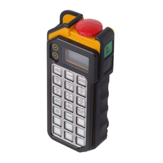
Diagnostic LED Table 2. Functional Description Some basic features of the ERGO F21 transmitter are an ON-OFF-ON maintain toggle switch, pushbutton controls, STOP button, LED status and feedback indicators, graphic display and half duplex transceiver. The graphic display provides real-time visual information during operation of the transmitter. It can be used to change configuration settings, provide two-way feedback and display transmitter diagnostic information such as battery life, signal strength and button status. -
Page 9: Operating Your Transmitter
2. Insert a battery adapter with fresh batteries into the battery compartment of the transmitter. 3. Make sure that the STOP switch cap is present on the ERGO F21 unit and that no button is pressed. 4. Turn ON the receiver. -
Page 10: Stopping The Radio Remote Control
The Low Battery detection threshold can be configured through the ‘Low Batt Warning’ field in the ‘RF’ tab on Hetronic PC-Link. In addition to low battery warning, a fixed critical battery level is also monitored. When critical battery level is reached, the RED Status LED will blink faster. -
Page 11: Powering Off The Transmitter
4) When the battery state of charge is low and the critical battery timer threshold has elapsed. 5.10 Belts The practical belt on the ERGO F21 unit allows the user to clip on the appropriate belt for ease of access and operator safety during operation. -
Page 12: Generic Radio Remote System Functionalities
PC H-Link tool allows one or more and up to three digital control functions to be associated with the same push button switch. This is valid for all single step buttons on the ERGO F21 unit, front panel buttons, the two LCD buttons and also the left and... -
Page 13: Figure 3. Pc H-Link Assignment Of Digital Control Channels To Push Buttons
USER MANUAL | ERGO F21 Figure 3. PC H-Link assignment of digital control channels to push buttons... -
Page 14: Setting Up Your Ergo F21 Transmitter For Operation
7.2.1 Radio Settings The Ergo F21 coder is designed with the possibility to connect one radio frequency (RF) module operating in the sub 1GHz range or 2.4GHz. When the radio module is plugged directly on to the coder (onboard), the user may select the frequency channel or group to use for communication. -
Page 15: Telegram
7.4 LCD Backlight The LCD backlight can be enabled or disabled through PC H-Link tool. The option works only on ERGO F21 units equipped with an LCD. It is also possible to associate one or more digital function with the backlight trigger such that the LCD backlight will turn on whenever the digital signal corresponding to the pressed button is activated. -
Page 16: Lcd Welcome Note
7.5 LCD Welcome Note ERGO F21 units equipped with display offer the product owner to configure a custom welcome note message on the display as part of the power up sequence of the unit. The configuration of the welcome note is possible through the Feedback tab on PC H-Link configurator. -
Page 17: Figure 10. Lcd Text Mode
It is also possible to set the LCD feedback mode to standard. This mode allows graphic configuration using LCDxA PC H-Link library. Consult Hetronic or your nearest Hetronic dealer for a copy of this library or additional information. Figure 11. Standard Graphic display programming mode using PC H-Link LCDxA library... -
Page 18: Figure 12. Led Feedback Configuration
7.6.4 LED Feedback ERGO F21 allows programming of up to 10 feedback LEDs on the front panel. The configuration of LEDs and their ON/OFF/Blink pattern can be adjusted through the Feedback tab on PC H-Link configurator tool. It is also possible to configure each feedback LED with a slow or fast blink behaviour independently. -
Page 19: Theory Of Operation
Operation Your ERGO F21 transmitter works with a receiving device to transfer machine control commands via radio frequency to your machine. The transmitter electronically generates a carrier frequency that allows it to communicate with the receiver without the use of cables or wires. -
Page 20: Installing The Radio Remote Control
USER MANUAL | ERGO F21 9. I nstalling the Radio Remote Control The following instructions are recommended so as to set up a properly operating radio remote control system. The radio remote control must be installed by qualified personnel only. -
Page 21: Troubleshooting
If your ERGO F21 transmitter does not operate after normal start-up, follow the recommended troubleshooting sequence below to help isolate the cause and determine corrective action. If you need more information, contact your nearest Hetronic dealer. PROBLEM PROBABLE CAUSE... -
Page 22: Warranty, Service, Repairs And Maintenance
Hetronic may replace the product or faulty parts. Work under guarantee/warranty must be carried out by Hetronic, or by an authorized service centre specified by Hetronic. Any modification, reconstruction or extension of the systems without a written agreement of Hetronic may lead to the loss of your warranty and guarantee claims. -
Page 23: Regulatory Information
Annex I of the EU Council Directive 2014/30/EU referred to as EMC Directive. Chargers - Hetronic declares that the “Battery Charger UCH 2” is in accordance with 2006/42/EU article 2(c), are is designed for installation on machinery or other devices. Further, the above listed safety components meet the following directives at the time... -
Page 24: Industry Canada (Ic/Ised) Statement
USER MANUAL | ERGO F21 To comply with FCC RF exposure compliance requirements, this device and its antenna must not be co-located with, or operating in conjunction with, any other antenna or transmitter. This equipment has been tested and found to comply with the limits for a Class B digital device, pursuant to Part 15 of the FCC Rules. - Page 25 Technical information subject to change without notice. Hetronic reserves the right to discontinue, make changes to, and add improvements upon its standard products at any time without public notice or obligation. Hetronic disclaims liability for any claims or damages, whether regarding property, personal injury or...
-
Page 26: Definition Of Terms
USER MANUAL | ERGO F21 Appendix A Definition of terms The following terms are used throughout the ERGO F21 User Manual and may be unfamiliar to some operators. Term Definition baud rate The transmitting speed measured in bits per second. -
Page 27: Operator Safety Basics
Instructions, manuals, and safety warnings of the manufacturers of the equipment where Hetronic products are used, ▪ Plant safety rules and procedures of the employers and the owners of the facilities where the Hetronic products are being used, ▪ Occupational Health and Safety Administration (OSHA) regulations, ▪... - Page 28 USER MANUAL | ERGO F21 Transmitter Start-up and Safety Checklist Are batteries fully charged? Are all switch labels clear and legible? Is the transmitter free from cracks and damages? Are the battery enclosures free from cracks and damages? Is the STOP function working as it should be?
-
Page 29: Transmitter Specifications
USER MANUAL | ERGO F21 Transmitter Specifications Housing: Ergonomically designed PC-ABS blend housing, one-hand operation Environmental Protection: IP 65 (Exceeds Nema 12/13) Weight: Up to 400 g (14.2 oz.), including battery Dimensions: Height: 186 mm (7.3 in.) Width: 82 mm (3.2 in.) Depth: 39 mm (1.3 in.) -
Page 30: Figure 14. Inserting Battery
USER MANUAL | ERGO F21 Battery & Charger You may power your transmitter with disposable or rechargeable batteries. Both types use adapter cases that are inserted into the back of the transmitter. Follow the instructions below for your battery type. -
Page 31: Figure 15. 3.6V 2.75Ah Nimh Battery
AVOID ENVIRONMENTAL POLLUTION. Recycle your rechargeable batteries according to local recycling rules and regulations. If you have questions or problems operating your battery charger, please contact your nearest Hetronic dealer or service centre. Standard Hetronic rechargeable batteries are the Lithium–Ion type. These batteries have no “memory effect” when charging a battery that is not fully discharged. -
Page 32: Figure 16. Charger Plug Variations
USER MANUAL | UCH 2 CHARGER MINI UCH 2 Battery Charger Recharging your Batteries To charge the MINI battery, it must be removed from the transmitter by lifting it up and sliding it out of the battery compartment. Slide the battery in the charging unit until it clips in place and the yellow ‘CHARGE”... - Page 33 List of UCH 2 Charger Variants EXPLOSIVE GASES AND FLYING DEBRIS can cause death or serious injury. Use only Hetronic replacement rechargeable batteries. Use of unauthorized replacement batteries could cause a battery explosion resulting in injury or death of the operator or...
Need help?
Do you have a question about the ERGO F21 and is the answer not in the manual?
Questions and answers