Table of Contents
Advertisement
Operator Manual
www.hetronic.com
YOUR #1 PARTNER IN RADIO REMOTE CONTROLS
Hetronic USA
4300 Highline Blvd., Bldg. A
Oklahoma City, OK 73108
405-946-3574
Fax 405-946-3564
© 2004 Hetronic, Inc.
All rights reserved. No part of this publication may be reproduced, transmitted, transcribed, stored in a retrieval
system, or translated into any language in any form by any means without the written permission of Hetronic.
TG Systems
TG DIG-V1
Hetronic Canada
45 Sinclair Avenue
Halton Hills, Ontario L7G 4X4
+1-800-816-4459
Fax +1-905-702-0501
OPMN_TG_0001.0
6/04
Advertisement
Table of Contents

Related Manuals for HETRONIC TG DIG-V1


Summary of Contents for HETRONIC TG DIG-V1
- Page 1 © 2004 Hetronic, Inc. OPMN_TG_0001.0 All rights reserved. No part of this publication may be reproduced, transmitted, transcribed, stored in a retrieval 6/04 system, or translated into any language in any form by any means without the written permission of Hetronic.
-
Page 2: Table Of Contents
Production and System Numbers ..3 TG DIG-V1 Transmitter ....13 Unauthorized Replacement Parts ..3 Transmitter Setup. -
Page 3: Introduction
Thank you for purchasing the Hetronic radio remote Use only Hetronic replacement parts. The replacement control system. Hetronic radio remote controls are the of any part with anything other than a Hetronic highest caliber in remote control value, performance authorized replacement part may adversely affect the and safety. -
Page 4: Hetronic System Components
The E-Stop responds faster than any other function. When E-Stop is engaged, the system ignores any other The Hetronic radio remote control system consists of a signal that is transmitted. The problem must be receiver and transmitter with belt, battery charger, and corrected before the system will respond to any other two rechargeable batteries. -
Page 5: Safety
SAFETY SAFETY ALERT POSSIBLE SOURCES OF DANGER Look for this symbol to point out This system makes remote control via radio signals important safety precautions. They possible. However, the transmission of control mean: commands can take place around obstacles and out of the operator’s direct sight. -
Page 6: Receiver Installation
RECEIVER INSTALLATION RECEIVER COMPONENTS The receiver accepts commands from the remote control transmitter and interfaces with the crane controls to activate crane functions. Receiver components are shown below. Mounting dimensions are shown later in this section. WARNING: FAILURE TO FOLLOW INSTRUCTIONS could result in personal RX 14-0004 RECEIVER injury and/or damage to equipment. -
Page 7: Receiver Location
This number is required when protection from violent impact from debris or thrown Hetronic is called for any service or parts information. materials and is easily accessible. The receiver Be sure the decal is easily accessible when the housing is rated IP65 and can withstand direct water jet receiver is mounted to the equipment. -
Page 8: Rx 14-0004 Mounting Dimensions
5. Insert the mounting screws through the holes in the receiver housing and tighten into the mounting surface. 6. Please refer to the appropriate illustration for mounting dimensions. Contact Hetronic for more 90 mm (3.54 in) information or if you have questions. RX 20 Receiver Mounting Dimensions 7. -
Page 9: Standard External Antenna Installation
Hetronic or your dealer. NOTE: Improper installation of the antenna will cause When using a GainFlex antenna, there must be no intermittent signal loss. -
Page 10: Connect Electrical Wiring
CONNECT ELECTRICAL WIRING TG Dig-V1 System with RX 14-0004 Outputs Connect all remaining wires (power supply, E-stop start/horn, etc.) according to the wiring diagram of the crane/machine and the radio remote control. The receiver outputs are shown in the following illustrations. -
Page 11: Tg Dig-V1 With Rx 20 Outputs
TG Dig-V1 System with RX 20 Outputs REL6-RX DK9 DK25 DK10 Emergency DK26 Stop DK27 DK28 S9-1 S9-2 S10-1 DK3 DK11 DK4 DK12 DK5 DK13 DK6 DK14 DK7 DK15 DK8 DK16 1 2 3 4 5 6 S10-2 S11-1 S12-1... -
Page 12: Overhead Traveling Crane (Mat. Handl.)
Typical Overhead Traveling Crane Supply, Start, & E-Stop Wiring NOTE: Material Handling Only. 1 2 3 4 5 6 1 2 3 4 5 6 7 8 9 10 11 12 1 2 3 4 5 6 7 8 9 10 1 2 3 4 5 6 MAINLINE CONTACTOR... -
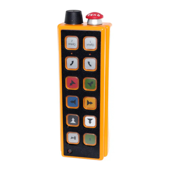
Page 13: Tg Transmitter
TG TRANSMITTER Each Hetronic radio remote control system is delivered with two fully charged NiMH batteries. One is inserted CAUTION: AVOID INJURY OR DAMAGE - in the battery compartment located on the back of the Operating the transmitter without its antenna transmitter. -
Page 14: Transmitter Setup
TRANSMITTER SETUP This section describes the steps to properly label the 3. Place the new label into the pushbutton cover transmitter for operation. face down, so the label shows when the cover is turned right-side up. Placing the Pushbutton Labels 4. -
Page 15: Led Designations & Layout
LED Designations and Layout 1. CPU Yellow LED 2. Transmission Green LED 3. E-stop Fault Red LED 4. Telegram Type Red LED 5. E-stop Relay Activated Red LED 6. Output Relays K1 - K20 Activated Red LEDs Emergency Stop 1 2 3 4 5 6 1 2 3 4 5 6 7 8 1 2 3 4 5 6 1 2 3 4 5 6 7 8... -
Page 16: Operation
IMPORTANT: Never operate a transmitter with worn or transmitter is not attached to the operator, the key damaged parts. Replace immediately with only switch should be removed and stored in a secure Hetronic parts. Contact Hetronic or your Dealer. place. -
Page 17: To Stop In An Emergency
OR DEATH. Switch the crane/machine "OFF" 4. Refer to crane/machine’s operator manual for if there is a fault or any problems with the further instructions. safety check. Contact Hetronic or your dealer SAFE MODE immediately to repair the system. NEVER operate the crane/machine when the... -
Page 18: Charging The Battery
European AC US/Japan AC Optional Cigarette Lighter Adapter Battery Charger Power Options Hetronic Battery Information Standard Hetronic rechargeable batteries are the nickel metal hydride type. These batteries have no “memory effect” when charging a battery that is not fully discharged. -
Page 19: Rf Modules
The frequency channel of the transmitter must be set to the frequency channel of the receiver it is going to control. Each Hetronic radio remote control system is pre-set at the factory with the correct frequency channel in the transmitter and receiver. The... -
Page 20: Cs 458 Rf-Synthesizer
& Jumper Settings May 2003 The Hetronic Radio Remote Control System address code and frequency channel are set at the factory. The address code and frequency channel may need to be set if you have purchased a replacement or spare transmitter. -
Page 21: Cs 447 Rf-Synthesizer
& Jumper Settings May 2003 The Hetronic Radio Remote Control System address code and frequency channel are set at the factory. The address code and frequency channel may need to be set if you have purchased a replacement or spare transmitter. -
Page 22: Cs 434 Rf-Synthesizer
SALS_009.0_CS 434 May 2003 The Hetronic Radio Remote Control System address code and frequency channel are set at the factory. The address code and frequency channel may need to be set if you have purchased a replacement or spare transmitter. -
Page 23: Std-402 Rf-Synthesizer
STD-402 RF-SYNTHESIZER Description of the Transmitter Module The RF unit has a permanently affixed antenna and Description of the Functions receives input power and TTL data by the 3-pin Dubox The frequency range of the STD-402 synthesizer connector (see picture). extends from 429.2500 MHz to 429.7375 Mhz. -
Page 24: Cs 429 Rf-Synthesizer
STD-402 429 MHZ Hetronic CS 429 Frequency & DIP Switch Settings SALS_010.0_CS 429 May 2003 Channel Channel Scan 7, 11, 15, 19, 23, 27, 31, 35, 39, 43 8, 12, 16, 20, 24, 28, 32, 36, 40, 44 9, 13, 17, 21, 25, 29, 33, 37, 41, 45... -
Page 25: Troubleshooting
Hetronic system on page 14 of this manual that shows the location of labels. each diagnostic LED. • Are there other Hetronic systems at or near the machine site? Transmitter • Is the EMERGENCY STOP pushbutton pulled out? •... - Page 26 Check wiring on key switch. Replace key not transmit (Power switch, wiring or contact element. LED not flashing) Coder board failure Contact Hetronic or your Dealer. Transmitter is E-Stop switch engaged Pull out the E-Stop pushbutton and press the Start pushbutton...
- Page 27 External antenna (if used) has loose Tighten antenna and ground connection. connection, poor grounding or Contact Hetronic or your Dealer for more interference information on external antennas. Surge suppressors not installed on Install RC type surge suppressors on all...
-
Page 28: Specifications
Up to 20 hours for CS 434, CS 447 30VDC/240VAC and CS 458 2 NO/NC Potential-free relays at 8A Up to 18 hours for STD 402 30VDC/240VAC TG DIG-V1 BATTERY CHARGER Functions E-Stop pushbutton Key power switch Charging current Normal: 200 mAh... -
Page 29: Installation / Safety Data Sheet
Hetronic assumes no responsibility for the correct operator manuals. installation of the radio remote control system. The equipment operator must ensure that the radio remote control system and the crane/machine operate correctly together. -
Page 30: Definitions & Awg Metric Conversions
DEFINITIONS Acoustic signal A buzzer or other sound intended to be heard as an alert. Analog signal Proportional - stepless or infinite control Belly box A transmitter that is secured to the front of the operator’s body by a belt, strap or breastplate/harness. -
Page 31: Abbreviations
ABBREVIATIONS Analog to digital conversion Analog channel (German: Analog Kanal) Ampere American Wire Gauge Bits per second Central Processing Unit Digital channel (German: Digital Kanal) Electromagnetic compatibility Electromagnetic immunity EPROM Electrical programmable read-only memory Frequency modulation Ground High frequency Kilohertz Light emitting diode Lift to operate Milliampere hours... -
Page 32: Warranty
F.O.B: Hetronic USA, Inc. Oklahoma City, Oklahoma Hetronic, Inc., hereafter referred to as Company, guarantees all items manufactured by it against any defects of material and/or workmanship for a period of one year from the date of shipment. Company makes NO OTHER WARRANTY, EXPRESSED OR IMPLIED, AS TO THE MERCHANTABILITY OR FITNESS OF THE ITEMS FOR THEIR INTENDED USE OR AS TO THEIR PERFORMANCE.
Need help?
Do you have a question about the TG DIG-V1 and is the answer not in the manual?
Questions and answers