Table of Contents
Advertisement
Quick Links
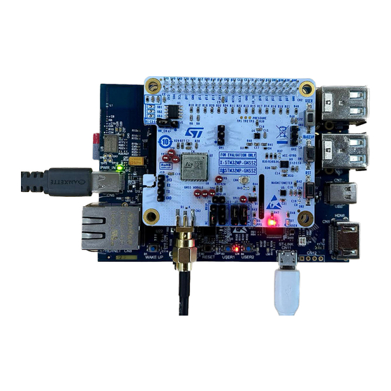
Getting started with X-STM32MP-GNSS2 expansion board for the
Introduction
The
X-STM32MP-GNSS2
multisensor expansion board embeds the following devices:
•
The
Teseo-LIV4F
module for Low power GNSS communication along with sensor for position accuracy.
•
The
ISM330DHCX
iNEMO 3-axis accelerometer and 3-axis gyroscope
•
The
IIS2MDC
3-axis magnetometer
•
The
ILPS22QS
pressure sensor
•
Switches and LEDs are present
The
X-STM32MP-GNSS2
interfaces with the
and GPIO peripherals.
The
X-STM32MP-GNSS2
expansion board is compatible with both the
connector layout.
UM3283 - Rev 1 - December 2023
For further information contact your local STMicroelectronics sales office.
STM32MP157F-DK2
microprocessor via a 40-pin GPIO connector, using I²C, SPI,
Figure 1.
X-STM32MP-GNSS2 expansion board
STM32MP157F-DK2 discovery kit
STM32MP157F-DK2
and Raspberry Pi GPIO expansion
UM3283
User manual
www.st.com
Advertisement
Table of Contents

Related Manuals for ST X-STM32MP-GNSS2


Summary of Contents for ST X-STM32MP-GNSS2
-
Page 1: Figure 1. X-Stm32Mp-Gnss2 Expansion Board
UM3283 User manual Getting started with X-STM32MP-GNSS2 expansion board for the STM32MP157F-DK2 discovery kit Introduction X-STM32MP-GNSS2 multisensor expansion board embeds the following devices: • Teseo-LIV4F module for Low power GNSS communication along with sensor for position accuracy. • ISM330DHCX iNEMO 3-axis accelerometer and 3-axis gyroscope •... -
Page 2: Overview
3.3 V supply through the STM32MP157F-DK2 GPIO connector. The figure below shows the component placement on the board. Figure 2. X-STM32MP-GNSS2 component placement details X-STM32MP-GNSS2 is a 40-pin connector expansion board for STM32MP157F-DK2 discovery kit with... -
Page 3: System Requirements
UM3283 Overview Figure 3. System Block diagram System requirements To test the X-STM32MP-GNSS2, you need: • X-STM32MP-GNSS2 expansion board • STM32MP157F-DK2 discovery kit • a laptop/desktop (with Windows 10 or above) • a USB Type-A to micro-B USB cable (for connection as a virtual serial device, if required) •... -
Page 4: Jumper Settings For Programming Teseo-Liv4F
Pin 1 can be identified as a rectangular footprint pad on both boards. Note: Boards can damage if not connected properly. Figure 4. X-STM32MP-GNSS2 connected to STM32MP157F-DK2 Step 3. Power the STM32MP157F-DK2 using the USB Type-C® cable. Step 4. -
Page 5: Component Description
UM3283 Component description Component description The board comprises the following key devices: EEPROM section M24C32 is a 32-Kbit I²C-compatible EEPROM (electrically erasable programmable memory) organized as 4 K × 8 bits. Table 2. M24C32-R package details Features Description Order code M24C32-RMN6TP Package SO-8... -
Page 6: Teseo-Liv4F Module Section
UM3283 Component description Teseo-LIV4F module section: Teseo-LIV4F module is based on the TESEO IV single die GNSS receiver IC working simultaneously on multiple constellations GPS/Galileo/Glonass/BeiDou/QZSS/IRNSS) able to provide positioning data. It is a low- power tiny GNSS receiver. Within its 9.7 x 10.1 mm tiny size, the Teseo-LIV4F offers superior accuracy as it has a temperature compensated Crystal oscillator (TCXO) and a reduced time to first fix (TTFF) relying to its dedicated... -
Page 7: Pressure Sensor Ilps22Qs
UM3283 Component description Features Description Package LGA-14L Operating voltage 1.71 V to 3.6 V Figure 7. ISM330DHCXTR circuit Pressure sensor ILPS22QS ILPS22QS is an ultracompact piezoresistive absolute pressure sensor, which functions as a digital output barometer, supporting dual full-scale up to user-selectable 4060 hPa. An embedded Qvar (electric charge variation detection) channel can be enabled for sensing in applications such as tap, double tap, long press, and L/R - R/L swipe. -
Page 8: Magnetometer Iis2Mdc
UM3283 Component description Figure 8. ILPS22QSTR circuit Magnetometer IIS2MDC IIS2MDC is a high-accuracy, ultra-low-power 3-axis digital magnetometer. The IIS2MDC has a magnetic field dynamic range up to ±50 gausses. IIS2MDC includes an I²C serial bus interface that supports standard, fast mode, fast mode plus, and high- speed (100 kHz, 400 kHz, 1 MHz, and 3.4 MHz) and an SPI serial standard interface. -
Page 9: Leds And Switches
UM3283 Component description LEDs and switches Three LEDs are used as an output to indicate to the user the functioning of the module. A red LED glows constantly indicating an adequate power supply is available to the board. A green LED blinks continuously to indicate the functioning of PPS (pulse per second). -
Page 10: Table 8. Gpio Connector Pin Configuration
UM3283 Component description Figure 11. GPIO Connector Table 8. GPIO connector pin configuration Pin No Name STM32MP157F-DK2 Pin No Name STM32MP157F-DK2 I2C_SDA PA12 / I2C5_SDA I2C_SCL PA11 / I2C5_SCL TESEO- IIS2MDC_INT_DRDY PA8/ MCO1 PB10 / USART3_TX LIV4F_UART_RX TESEO- PB12 / USART3_RX LIV4F_UART_TX TESEO-LIV4F_WAKEUP PG8 / USART3_RTS... - Page 11 UM3283 Component description Pin No Name STM32MP157F-DK2 Pin No Name STM32MP157F-DK2 PF5/ SDMMC3_D2 PI6 / SAI2_SDA PF11 / SAI2_SDB UM3283 - Rev 1 page 11/29...
-
Page 12: Schematic Diagrams
Schematic diagrams Figure 12. X-STM32MP-GNSS2 schematic diagram (1 of 8) P a ge 3_Conne ctor GP IO_Expa ns ion_Conne ctor LED_US ER LED_US ER EEP ROM_ID_S D EEP ROM_ID_S D S WITCH_US ER S WITCH_US ER EEP ROM_ID_S C EEP ROM_ID_S C... -
Page 13: Figure 13. X-Stm32Mp-Gnss2 Schematic Diagram (2 Of 8)
Figure 13. X-STM32MP-GNSS2 schematic diagram (2 of 8) S B1 S B2 S B3 Ope n Ope n Ope n 100nF 3.9K 3.9K EEP ROM_ID_S C S CL EEP ROM_ID_S D VS S S DA M24C32-RMN6TP J R1 S HUNT 2.54 mm. -
Page 14: Figure 14. X-Stm32Mp-Gnss2 Schematic Diagram (3 Of 9)
Figure 14. X-STM32MP-GNSS2 schematic diagram (3 of 9) 100nF 100nF 100nF S DA S CL TP 1 TP 2 100nF TP 3 ID_S D ID_S C HEADER2X20 1.5k 1.5k S DA I2C_S DA TES EO-LIV4F_RES ET S CL I2C_S CL... -
Page 15: Figure 15. X-Stm32Mp-Gnss2 Schematic Diagram (4 Of 8)
Figure 15. X-STM32MP-GNSS2 schematic diagram (4 of 8) J R2 S HUNT 2.54 mm. TES EO-LIV4F_UART_TX CON_TX HEADER1X3 S MA_HRZ J R3 UART-TX RF_IN S HUNT 2.54 mm. TES EO-LIV4F_UART_RX TP 4 UART-RX RES ERVED2 CON_RX HEADER1X3 TP 5 P RG... -
Page 16: Figure 16. X-Stm32Mp-Gnss2 Schematic Diagram (5 Of 8)
Figure 16. X-STM32MP-GNSS2 schematic diagram (5 of 8) IS M330DHC_3V3 I2C_S CL IS M330DHC_3V3 IS M330DHC_3V3 I2C_S DA S DO/S A0 S DO_Aux S Dx OCS _Aux IS M330DHC_INT2 S Cx INT2 IS M330DHC_3V3 IS M330DHC_INT1 INT1 IS M330DHCXTR 4.7K... -
Page 17: Figure 18. X-Stm32Mp-Gnss2 Schematic Diagram (7 Of 8)
Figure 18. X-STM32MP-GNSS2 schematic diagram (7 of 8) IIS 2MDC_3V3 I2C_S CL IIS 2MDC_INT_DRDY S CL/S P C INT/DRDY NC_1 GND_2 IIS 2MDC_3V3 IIS 2MDC_3V3 I2C_S DA S DA/S DI/S DO VDD_IO NC_2 GND_1 NC_3 IIS 2MDCTR 100nF 100nF 10uF... -
Page 18: Figure 19. X-Stm32Mp-Gnss2 Schematic Diagram (8 Of 8)
Figure 19. X-STM32MP-GNSS2 schematic diagram (8 of 8) LED GREEN TP 11 TES EO-LIV4F_P P S 2S TR1160 U.FL-R-S MT-1(10) LED_US ER 4.7K S WITCH_US ER S W3 100nF S P S T S W LED RED LED YELLOW STMicroelectronics and/or its licensors do not warrant the... -
Page 19: Bill Of Materials
UM3283 Bill of materials Bill of materials Table 9. X-STM32MP-GNSS2 bill of materials Item Q.ty Ref. Part/value Description Manufacturer Order code Battery Holder (Open) Coin, S8421-45R Harwin Inc. S8421-45R 20.0mm 1 Cell SMD (SMT) Tab C1 C2 C3 C4 CAP CER C5 C13 C14 Würth... - Page 20 UM3283 Bill of materials Item Q.ty Ref. Part/value Description Manufacturer Order code LED YELLOW Würth LED YELLOW CLEAR 0603 150060YS75000 Elektronik CONN 3-pin Male HEADER .100 Samtec Inc. TSW-103-07-F-S Header STR 3POS CONN 3-pin Male J6 J7 J8 J11 HEADER .100 Samtec Inc.
- Page 21 UM3283 Bill of materials Item Q.ty Ref. Part/value Description Manufacturer Order code RES SMD 22K OHM 5% 1/10W Vishay Dale CRCW060322K0JNEA 0603 RES SMD 0 TE Connectivity OHM JUMPER CRG0603ZR Passive Product 1/10W 0603 RES 300 OHM Stackpole R47 R48 RMCF0603FT300R 1% 1/10W 0603 Electronics Inc.
-
Page 22: Stm32Mp-Gnss2 Versions
X-STM32MP-GNSS2 versions PCB version Schematic diagrams Bill of materials X$STM32MP-GNSS2A X$STM32MP-GNSS2A schematic diagrams X$STM32MP-GNSS2A bill of materials 1. This code identifies the X-STM32MP-GNSS2 evaluation board first version. It is printed on the board PCB. UM3283 - Rev 1 page 22/29... -
Page 23: Regulatory Compliance Information
UM3283 Regulatory compliance information Regulatory compliance information Notice for US Federal Communication Commission (FCC) This kit is designed to allow: (1) Product developers to evaluate electronic components, circuitry, or software associated with the kit to determine whether to incorporate such items in a finished product and (2) Software developers to write software applications for use with the end product. -
Page 24: Testing And Certification
UM3283 Testing and certification Testing and certification Teseo-LIV4F module is CE-certified (2051-RED-222704). Refer to the device datasheet for further details. UM3283 - Rev 1 page 24/29... -
Page 25: Revision History
UM3283 Revision history Table 11. Document revision history Date Revision Changes 05-Dec-2023 Initial release. UM3283 - Rev 1 page 25/29... -
Page 26: Table Of Contents
X-STM32MP-GNSS2 versions ........ -
Page 27: List Of Tables
X-STM32MP-GNSS2 bill of materials ........ -
Page 28: List Of Figures
X-STM32MP-GNSS2 connected to STM32MP157F-DK2 ........ - Page 29 ST’s terms and conditions of sale in place at the time of order acknowledgment. Purchasers are solely responsible for the choice, selection, and use of ST products and ST assumes no liability for application assistance or the design of purchasers’...
Need help?
Do you have a question about the X-STM32MP-GNSS2 and is the answer not in the manual?
Questions and answers