Table of Contents
Advertisement
Quick Links
UM1943
User manual
Getting started with the X-NUCLEO-IHM07M1 motor driver
expansion board based on the L6230 for STM32 Nucleo
Introduction
The X-NUCLEO-IHM07M1 is a three-phase brushless DC motor driver expansion board based on the
L6230 for STM32 Nucleo. It provides an affordable and easy-to-use solution for driving three-phase
brushless DC motors in your STM32 Nucleo project. The X-NUCLEO-IHM07M1 is compatible with the
ST morpho connector and supports the addition of other boards which can be stacked onto a single
STM32 Nucleo board. The user can also mount the Arduino UNO R3 connector. The X-NUCLEO-
IHM07M1 is fully configurable and ready to support different closed loop control based on sensor or
sensorless mode control, and it is compatible with three shunt or single shunt current sense measuring.
The driver used on this STM32 Nucleo expansion board is the L6230, a DMOS fully-integrated driver for
three-phase brushless PMSM motors, assembled in a PowerSO36 package, with overcurrent and
thermal protection. This user manual describes the procedure to configure the X-NUCLEO-IHM07M1
expansion board to operate with an STM32 Nucleo board.
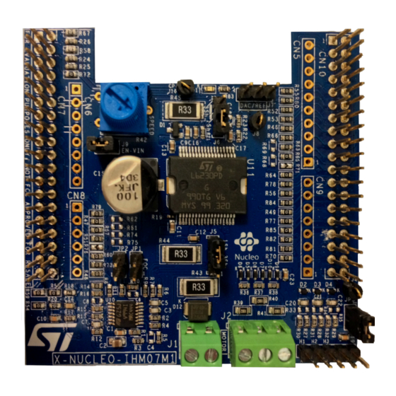
Figure 1: X-NUCLEO-IHM07M1 three-phase brushless DC motor driver expansion board based on L6230 for
STM32 Nucleo
September 2015
DocID028304 Rev 1
1/28
www.st.com
Advertisement
Table of Contents

Related Manuals for ST X-NUCLEO-IHM07M1


Summary of Contents for ST X-NUCLEO-IHM07M1
- Page 1 DC motors in your STM32 Nucleo project. The X-NUCLEO-IHM07M1 is compatible with the ST morpho connector and supports the addition of other boards which can be stacked onto a single STM32 Nucleo board. The user can also mount the Arduino UNO R3 connector. The X-NUCLEO- IHM07M1 is fully configurable and ready to support different closed loop control based on sensor or sensorless mode control, and it is compatible with three shunt or single shunt current sense measuring.
-
Page 2: Table Of Contents
Contents UM1943 Contents System introduction ................. 3 Main characteristics ................3 Target applications ................3 Getting started .................. 4 System architecture ................4 Building the system ................4 2.2.1 Hardware settings ................5 Board schematic ................10 Circuit description ................18 Power section –... -
Page 3: System Introduction
Cross-conduction protection Thermal measuring and overheating protection Full compatibility with ST Six Step or ST FOC control algorithms Full support for sensor and sensorless mode 3-shunt and 1-shunt configurable jumpers for motor current sensing ... -
Page 4: Getting Started
L6230 driver, which contains all the necessary active power and analog components to perform low voltage PMSM motor control. Motor - the X-NUCLEO-IHM07M1 is able to properly drive a low voltage BLDC/PMSM motor. Figure 2: Overall system architecture... -
Page 5: Hardware Settings
Getting started Figure 3: X-NUCLEO-IHM07M1 plugged on STM32 Nucleo The interconnection between the STM32 Nucleo and the X-NUCLEO-IHM07M1 has been designed for full-compatibility with many STM32 Nucleo boards and no solder bridge modification is required. When stacked, the system is ready to operate with the connection of a BLDC/PMSM motor. - Page 6 STM32 Nucleo board. All signals and power pins of the MCU are available on the ST morpho connector. For further details, please refer to user manual UM1724 (5.12 STMicroelectronics morpho connector) available on www.st.com.
- Page 7 UM1943 Getting started Connector Default Signal Solder bridge NC/PF7 IOREF PA13 RESET PA14 +3V3 PA15 Encoder A/Hall H1 Encoder/Hall PS voltage PC13 Blue button PC14 PC15 Curr_fdbk_PhA PH0/PF0/PD0 VBUS_sensing PH1/PF1/PD1 DAC_Ch R76 N.M. VLCD/VBAT BEMF2_sensing Temperature feedback PC1 or PB9 Curr_fdbk_PhB BEMF1_sensing PC0 or PB8...
- Page 8 Please refer to Table 9: Solder bridges in user manual UM1724 for further details Please refer to Table 9: Solder bridges in user manual UM1724 for further details U5V is 5 V power from ST-LINK/V2-1 USB connector and it rises before +5 V For STM32F302-Nucleo only:...
- Page 9 UM1943 Getting started For STM32F302-Nucleo only: - pin PA5 is on CN10/pin 30 and PB13 is on CN10/pin 11 - pin PA6 is on CN10/pin 28 and PB14 is on CN10/pin 13 - pin PA7 is on CN10/pin 26 and PB15 is on CN10/pin 13 For STM32F302-Nucleo only: - pin PA5 is on CN10/pin 30 and PB13 is on CN10/pin 11 - pin PA6 is on CN10/pin 28 and PB14 is on CN10/pin 13...
-
Page 10: Board Schematic
Board schematic UM1943 Board schematic Figure 5: X-NUCLEO-IHM07M1 schematic (1 of 8) External operational-amplifier 100nF10V 4.7uF 10V 2.2k 680pF 10V Vshunt_1 U10A Curr_fdbk1 Vshunt_1_GND TSV994IPT 2.2k 2.2k U10D TSV994IPT N.M. 100p F/6.3V 680pF 10V Overall AV=1.53 2.2k Vshunt_2 U10B Curr_fdbk2... - Page 11 UM1943 Board schematic Figure 6: X-NUCLEO-IHM07M1 schematic (2 of 8) VBUS SENSOR VIN+ 169K 1% Temperature feedba ck VBUS_SENS VBUS 10nF 10V 4.7nF/10V NTC 10K 9.31K 1% RS model 742-8420 Place d near the L6230 driver HALL/ENCODER SENSOR JUMPER A+/H1...
- Page 12 Board schematic UM1943 Figure 7: X-NUCLEO-IHM07M1 schematic (3 of 8) GSPG03092015DI1005 12/28 DocID028304 Rev 1...
- Page 13 UM1943 Board schematic Figure 8: X-NUCLEO-IHM07M1 schematic (4 of 8) GSPG03092015DI1010 DocID028304 Rev 1 13/28...
- Page 14 Board schematic UM1943 Figure 9: X-NUCLEO-IHM07M1 schematic (5 of 8) GSPG03092015DI1015 14/28 DocID028304 Rev 1...
- Page 15 UM1943 Board schematic Figure 10: X-NUCLEO-IHM07M1 schematic (6 of 8) USER C10_24 SPEED C10_22 VIN+ C7_24 JUMPER VIN 3A Open by default J27 on: 1) 12 VMAX on J26 2) JP5 (Nucleo pin 2, 3) 2) JP1 (Nucleo) removed BEMF six STEP...
- Page 16 Board schematic UM1943 Figure 11: X-NUCLEO-IHM07M1 schematic (7 of 8) GSPG03092015DI1410 16/28 DocID028304 Rev 1...
- Page 17 UM1943 Board schematic Figure 12: X-NUCLEO-IHM07M1 schematic (8 of 8) GSPG03092015DI1415 DocID028304 Rev 1 17/28...
-
Page 18: Circuit Description
Table 1: "Jumper settings". Figure 13: X-NUCLEO-IHM07M1 – power section The L6230 integrates a three-phase bridge which consists of six power MOSFETs. Using the N-channel power MOSFET for the upper transistors in the bridge requires a gate drive voltage above the power supply voltage. -
Page 19: Power Section - Overcurrent Detection (Ocp) And Current Sensing Measurement
UM1943 Circuit description Figure 14: X-NUCLEO-IHM07M1 – charge pump circuit GSPG14092015DI1535 Power section – Overcurrent detection (OCP) and current sensing measurement The L6230 driver implements overcurrent protection with an internal detection circuit that does not require an external resistor. The current is compared with an embedded current reference and the output generates a fault condition to the DIAG pin that goes to ground. - Page 20 Rsense (refer to the diagram below) and it is possible to choose between three-shunt or single-shunt configuration through the jumpers (J5, J6). For this setting please refer to Table 1: "Jumper settings". Figure 15: X-NUCLEO-IHM07M1 – current sensing circuit GSPG14092015DI1540 20/28 DocID028304 Rev 1...
-
Page 21: Analog Section - Hall/Encoder Motor Speed Sensor
BEMF1 BEMF2 BEMF3 GSPG15092015DI0650 Analog section – Bus voltage and temperature sensing circuit The X-NUCLEO-IHM07M1 expansion board provides the hardware for bus voltage sensing and temperature measurement. This signal is acquired respectively with a resistor divider DocID028304 Rev 1 21/28... - Page 22 Circuit description UM1943 and with an embedded NTC (placed closed to L6230 driver) as shown in the diagram that follows. Figure 18: X-NUCLEO-IHM07M1 – VBUS and temperature sensing circuit VIN+ 169K 1% Temperature feedback VBUS_SENS VBUS 10nF 10V NTC 10K 4.7nF/10V...
-
Page 23: Bom (Bill Of Material)
Capacitor 6.3V Ceramic X7R Ceramic Multilayer C20,C21,C22 10pF Capacitors C0G SMBD 7000 200 mA Signal Diode D2,D3,D4,D5,D6,D7,D8, ST SCHOTTKY BAT30KFILM 30V, 0.3A D9,D10 DIODE LED standard - SMD 2 WAYS STRIP JP1,JP2, JP3,J9 JUMPER LINE-MALE 2.54mm 2 way 3.81mm PCB... - Page 24 BOM (bill of material) UM1943 Item Part/ value Volt/Watt/Amp Type Tol. ELEVATED SOCKET MORPHO CN7,CN10 ST_morpho_19x2 CONNECTOR 38 PIN (19x2) 8 PIN ELEVATED CN6,CN9 CONN8 SOCKET 10 PIN ELEVATED CONN10 SOCKET 6 PIN ELEVATED CONN6 SOCKET R1,R4,R5,R6,R9,R10, R11,R12,R15,R16,R36, 2.2 kOhm 0.1W SMD RESISTOR R37,R38...
- Page 25 UM1943 BOM (bill of material) Item Part/ value Volt/Watt/Amp Type Tol. Transil™ SMBJ48A-TR Table 5: BOM (part 2) Item Package Manufacturer Orderable part number 0603 0805 C2012X7R1A475M125AC 0603 0603 0603 0603 0603 0603 0603 0603 SMD 10 mm x 10.5 mm Nichicon UUX1J101MNL1GS 0603...
- Page 26 BOM (bill of material) UM1943 Item Package Manufacturer Orderable part number 0603 0603 0603 0805 PANASONIC ERJT06J103V 0603 0603 0603 Bourns 3386P-1-104LF 2512 Panasonic ERJ1TRQFR33U 0603 0603 0603 0603 TSSOP STMicroelectronics TSV994IPT PowerSO STMicroelectronics L6230PD STMicroelectronics SMBJ48A-TR 26/28 DocID028304 Rev 1...
-
Page 27: Revision History
UM1943 Revision history Revision history Table 6: Document revision history Date Version Changes 17-Sep-2015 Initial release. DocID028304 Rev 1 27/28... - Page 28 ST products and/or to this document at any time without notice. Purchasers should obtain the latest relevant information on ST products before placing orders. ST products are sold pursuant to ST’s terms and conditions of sale in place at the time of order acknowledgement.
Need help?
Do you have a question about the X-NUCLEO-IHM07M1 and is the answer not in the manual?
Questions and answers