Advertisement
UM1857
User manual
Stepper motor driver expansion board based on L6474 for
STM32 Nucleo
Introduction
The X-NUCLEO-IHM01A1 is a stepper motor driving board based on the L6474.
It provides an affordable and easy-to-use solution for driving stepper motors in your STM32 Nucleo
project.
The advanced current control of the L6474 and the complete set of protections guarantee high
performance and robustness.
The X-NUCLEO-IHM01A1 is compatible with the Arduino UNO R3 connector on the ST Morpho
connector.
More boards of the same type can be stacked easily to drive up to three stepper motors with a single
STM32 Nucleo board.
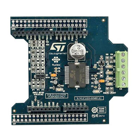
Figure 1: X-NUCLEO-IHM01A1 board
March 2015
DocID027377 Rev 1
1/9
www.st.com
Advertisement
Table of Contents

Related Manuals for ST X-NUCLEO-IHM01A1


Summary of Contents for ST X-NUCLEO-IHM01A1
- Page 1 The advanced current control of the L6474 and the complete set of protections guarantee high performance and robustness. The X-NUCLEO-IHM01A1 is compatible with the Arduino UNO R3 connector on the ST Morpho connector. More boards of the same type can be stacked easily to drive up to three stepper motors with a single STM32 Nucleo board.
-
Page 2: Table Of Contents
Contents UM1857 Contents Getting started ................3 Hardware description and configuration ........4 Selecting the chip select and clock lines of the SPI ......6 Multi motor configuration ..............6 Revision history ................8 DocID027377 Rev 1... -
Page 3: Getting Started
UM1857 Getting started Getting started The X-NUCLEO-IHM01A1 expansion board is a stepper motor driver covering a wide range of applications. The maximum ratings are: Power stage supply voltage (VS) from 8 V to 45 V Motor phase current up to 3 A rms To start your project with the board: Check the jumper position in accordance with your configuration (see ). -
Page 4: Hardware Description And Configuration
Figure 2: Jumpers and connectors position The following tables provide the connector details for the Arduino UNO R3 and ST Morpho, respectively. Table 1: Arduino UNO R3 connector table... - Page 5 Section 2.1: "Selecting the chip select and clock SPI CS lines of the SPI" Notes: All the non-listed pins are not connected. Table 2: ST Morpho connector table Connector Signal Remarks Ground Section 2.1: "Selecting the chip select and clock SPI SCK lines of the SPI"...
-
Page 6: Selecting The Chip Select And Clock Lines Of The Spi
Hardware description and configuration UM1857 Selecting the chip select and clock lines of the SPI The chip select and the clock lines of the SPI interface can be selected through dedicated resistors as indicated in Table 3: "Chip select line selection" Table 4: "Chip select line selection". - Page 7 UM1857 Hardware description and configuration Table 6: Multi-motor setup with alternative SPI clock line Mounted resistors Number of motors Board STCK\\DIR (0R) 1 (bottom) PWM1\\DIR1 R1, R4, R7, R10 2 (top) PWM3\\DIR2 R2, R6, R8, R12 DocID027377 Rev 1...
-
Page 8: Revision History
Revision history UM1857 Revision history Table 7: Document revision history Date Revision Changes 16-Mar-2015 Initial release. DocID027377 Rev 1... - Page 9 ST products and/or to this document at any time without notice. Purchasers should obtain the latest relevant information on ST products before placing orders. ST products are sold pursuant to ST’s terms and conditions of sale in place at the time of order acknowledgement.
Need help?
Do you have a question about the X-NUCLEO-IHM01A1 and is the answer not in the manual?
Questions and answers