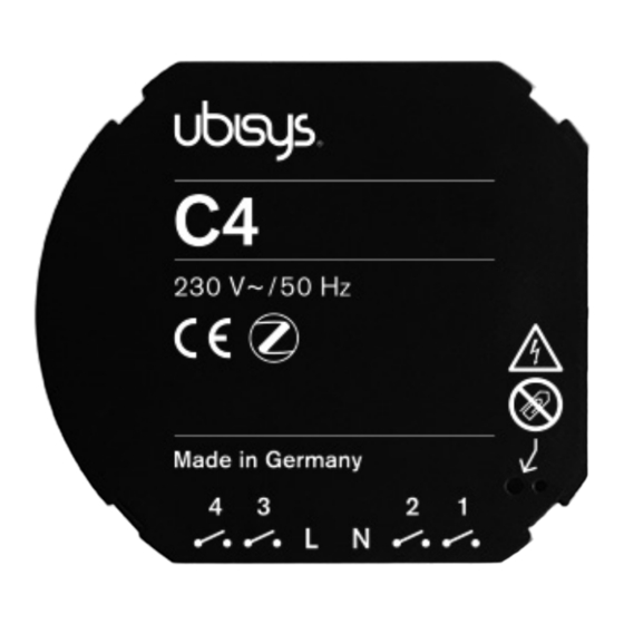
Ubisys C4 Integrator Manual

Ubisys C4 Integrator Manual

Zigbee device physical input configurations
Hide thumbs Also See for C4:

Advertisement

Quick Links

ZIGBEE DEVICE PHYSICAL INPUT CONFIGURATIONS
INTEGRATOR'S GUIDE

Advertisement

Table of Contents
loading
Need help?

Need help?

Do you have a question about the C4 and is the answer not in the manual?

Questions and answers

Summary of Contents for Ubisys C4

  • Page 1 ZIGBEE DEVICE PHYSICAL INPUT CONFIGURATIONS INTEGRATOR’S GUIDE...
  • Page 2: Table Of Contents

    Table of Contents 1. Overview ................ ...
  • Page 3: Overview

    1. Overview This document provides guide lines and reference configurations for the physical inputs of ubisys ZigBee devices, like C4, D1(-R), S1(-R), S2(-R) and J1(-R). These are the same configurations offered via the ubisys Smart Home app for iOS and Android.
  • Page 4: Introduction

    2. Introduction Most ubisys ZigBee devices with physical input contacts allow very flexible configuration of those inputs. For example, a mechanical switch with two stable positions can be connected to a single input and the input configured to send on commands in one position and off commands the other position, or toggle commands in each position.
  • Page 5: Recipes

    3. Recipes 3.1. General Overview Please make yourself familiar with the ubisys device setup cluster first. A description of this cluster is available in the Technical Reference manuals of ubisys C4, D1(-R), S1(-R), S2(-R) and J1(-R). In a nutshell, this cluster allows configuration of binary inputs. It maps state transitions, e.g. “released” to “pressed”, to over-the-air application layer commands, e.g.
  • Page 6: Example

    “toggle” command. 3.3.1. Example This would be a configuration for C4, which assigns each of the four inputs as a stationary switch (two stable positions) to a corresponding on/off cluster instance on the primary, secondary, tertiary, and quaternary level control switch endpoints.
  • Page 7 #1: six bytes  5 InputAndOptions: 0x00  6 Transition: released -> pressed  7 Source: Endpoint #1 (hosts primary on/off client cluster on C4)  8 06 00 Cluster ID: 0x0006 - on/off  9 ZCL Command Template: Toggle element #2: six bytes InputAndOptions: 0x00 Transition: any ->...
  • Page 8: Single Stationary Switch As On/Off Switch

    “off” command. 3.4.1. Example This would be a configuration for C4, which assigns each of the four inputs as a stationary switch (two stable positions) to a corresponding on/off cluster instance on the primary, secondary, tertiary, and quaternary level control switch endpoints.
  • Page 9 #1: six bytes  5 InputAndOptions: 0x00  6 Transition: released -> pressed  7 Source: Endpoint #1 (hosts primary on/off client cluster on C4)  8 06 00 Cluster ID: 0x0006 - on/off  9 ZCL Command Template: On element #2: six bytes InputAndOptions: 0x00 Transition: any ->...
  • Page 10: Single Momentary Switch As Timed On/Off Switch

    3.5.1. Example This would be a configuration for C4, which assigns each of the four inputs as a momentary switch (one stable position) to a corresponding on/off cluster instance on the primary, secondary, tertiary, and quaternary level control switch endpoints.
  • Page 11: Example

    #1: 11 bytes  5 InputAndOptions: 0x00  6 Transition: released -> pressed  7 Source: Endpoint #1 (hosts primary on/off client cluster on C4)  8 06 00 Cluster ID: 0x0006 - on/off  9 ZCL Command Template: On with timed off ZCL Command Template: On/off Control field = 0 B0 04 ZCL Command Template: On Time field = 0x04b0 = 1200 * 0.1s = 120s...
  • Page 12: Single Momentary Switch (Push Button) As Dimmer Switch

    #1: 11 bytes  5 InputAndOptions: 0x00  6 Transition: released -> pressed  7 Source: Endpoint #2 (hosts primary on/off client cluster on C4)  8 06 00 Cluster ID: 0x0006 - on/off  9 ZCL Command Template: On with timed off ZCL Command Template: On/off Control field = 0 B0 04 ZCL Command Template: On Time field = 0x04b0 = 1200 * 0.1s = 120s...
  • Page 13 Transition: pressed -> kept pressed, has alternate Source: Endpoint #2 (hosts primary level control client cluster on   08 00 Cluster ID: 0x0008 – level control 05 00 32 ZCL Command Template: Move with on/off, upwards, rate = 50 element #3: eight bytes InputAndOptions: 0x00 Transition: pressed ->...
  • Page 14: Double Momentary Switch (Push Buttons) As Dimmer Switch

    3.7. Double Momentary Switch (Push Buttons) as Dimmer Switch Related C++ class: CZigBeeDeviceSetupInputPatternDoublePushLevel. This is a more complex recipe designed for dimming a light, or generally speaking adjusting the level (intensity, speed, brightness, …) of a level controllable output utilizing two momentary switches (push buttons, one stable position).
  • Page 15: Double Momentary Switch (Push Buttons) As Shutter Switch

     1 element type: 0x41 (raw data)  2 06 00 element count: 0x0006 (6 entries)  3  4 element #1: six bytes  5 InputAndOptions: 0x00  6 Transition: pressed -> released  7 Source: Endpoint #2 (hosts primary on/off client cluster on D1)  8 06 00 Cluster ID: 0x0006 - on/off  9...
  • Page 16: Examples

    up direction, another one for the down direction. The idea is that each transition from the released state to the pressed state fires a “move up/open” command for the first button (“move down/close” command for the second button), and each transition from the pressed to the released state fires a “stop”...
  • Page 17: Examples

    Here, the blind moves as long as either switch is turned on. As soon as it is turned off, motion stops. The same approach can be applied to a C4, which allows two connect four switches and thus provides two window covering controllers (or a mix of one window covering controller plus one or two other functions).
  • Page 18: Example

    “recall scene” command for another scene. 3.10.1. Example This would be a configuration for C4, which assigns each of the four inputs as a stationary switch (two stable positions) to a corresponding scene cluster instance on the primary, secondary, tertiary, and quaternary level control switch endpoints.
  • Page 19: Single Momentary Switch (Push Button) As Scene Selector Switch

    3.11.1. Example This would be a configuration for C4, which assigns each of the four inputs as a stationary switch (two stable positions) to a corresponding scene cluster instance on the primary, secondary, tertiary, and quaternary level control switch endpoints. Each switch can recall two separate scenes (they need not address the same group).
  • Page 20 #2: six bytes InputAndOptions: 0x00 Transition: pressed -> kept-pressed Source: Endpoint #1 (hosts primary scene client cluster on C4) 05 00 Cluster ID: 0x0005 - scenes 05 9a 78 bc ZCL Command Template: Recall scene, group ID = 0x789a, scene ID =  ...
  • Page 21 & binding. For the raw functionality, it is not strictly required, though. [2] Qualified customers may license C (at least C11 language support is required) and Java classes from ubisys, which help with identification and assembly of usage patterns.
  • Page 22: History

    4. Revision History Revision Date Remarks 01/24/2013 Initial Version 12/19/2014 Added advanced support for recall scene command. Recall scene commands are now always sent to the group ID in the payload and don’t require an entry in the binding table 11/25/2014 Preliminary version (for internal use only).
  • Page 23: Contact

    5. Contact ubisys technologies GmbH Neumannstr. 10 40235 Düsseldorf Germany T: +49. 211. 54 21 55 - 19 F: +49. 211. 54 21 55 - 99 www.ubisys.de info@ubisys.de...

This manual is also suitable for:

D1D1-rS1S1-rS2S2-r ... Show all

Table of Contents