Ubisys S1-R Quick Start Manual
Radio linked with power consumption measurement
Hide thumbs
Also See for S1-R:
- Quick start manual (2 pages) ,
- Reference manual (40 pages) ,
- Integrator manual (23 pages)
Advertisement
Quick Links
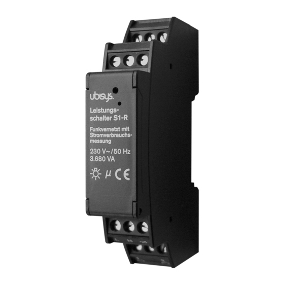
Power switch S1-R
Radio linked with power consumption measurement
Specifications
The power switch S1-R is a radio controlled universal switch actuator with
integrated power consumption measurement. In the current flush mount
version, it is compatible to standard switch boxes and fully integrates into the
rest of your smart home. It is not only suitable for new buildings, but also for
existing buildings, because retrofitting has, due to use of radio technology,
no special requirements to the electrical installation. For new buildings and
renovations, it helps reducing both planning and cabling costs. The system
can gradually be extended by adding new components. Determine scope and
timing at any time by yourself.
The power switch S1-R offers full functionality when combined with other
components of the ubisys smart home product line and allows for example:
•
Freely configurable assignments between control elements and consu-
mers
•
Scenes and group controlling
•
Time and event controlled actions
•
Continuous metering
•
Surveillance
•
Controlling via smart home display, smartphone app or, as usual, via
button or switch
More information about the features of the ubisys smart home product line
can be found at www.ubisys.de.
Installation
The power switch S1-R meets the requirements of DIN 43880 and is
designed for installation in fuseboxes, mounted on cap rails according to
EN50022.
Leistungs-
Leistungs-
schalter S2-R
schalter S1-R
Leads:
Funkvernetzt mit
Funkvernetzt mit
Stromverbrauchs-
Stromverbrauchs-
messung
messung
230 V~ /50 Hz
230 V~ / 50 Hz
(1 TE)
2 x 500 VA
3.680 VA
18 mm
Leistungs-
schalter S2-R
Funkvernetzt mit
Stromverbrauchs-
messung
230 V~ / 50 Hz
2 x 500 VA
The power switch S1-R retains its switch position when disconnected from
power. The switch position is undefined by delivery; i. e. the switching output
can be conductively connected to the phase L!
During installation, the general risks of household voltage networks have to
be noted!
Basic ZigBee Commissioning
The device joins an open ZigBee network when it is factory new and power
is applied.
Jalousie-
steuerung J1-R
Dimensions:
Funkvernetzt mit
Stromverbrauchs-
messung
230 V~/50 Hz
(1 TE)
500 VA
60,5 mm
18 mm
Leistungs-
schalter S1-R
Funkvernetzt mit
Stromverbrauchs-
messung
230 V~ / 50 Hz
3.680 VA
Factory Reset
Power-Cycle Sequencing Factory Reset: It is possible to instigate a factory
reset using a special power-cycle sequence. This is equivalent to selecting
menu item #5, with the advantage that you need no access to the device
itself (only to its power supply).
1.
Power the device for at least four seconds.
2.
Interrupt the power supply for at least a second.
3.
Reapply power for less than two seconds but more than half a second.
Notice that at the end of this cycle, the device is off and should remain off for
at least a second.
4.
Repeat the previous step two more times, for a total of three short
power cycles.
5.
Apply power to the device and leave it powered on. The device will now
factory reset and reboot.
Factory Reset via Button: To reset the device to its factory fresh settings
(e.g. in order to join it to another network afterwards), press the button in the
larger of the two holes on the front for more than 10 seconds until the LED
starts flashing rapidly. * )
Only use the electrically isolated tool provided with the device to press the
button in the hole.
Button
LED
Leistungs-
schalter S2-R
Funkvernetzt mit
Stromverbrauchs-
messung
*) If the device has legacy firmware this feature might not be available. In this
230 V~ /50 Hz
case, keep the button pressed for one second, until the LED flashes three
2 x 500 VA
times and then blinks once every second. Then press the button four times
for less than a second, until the LED flashes five times, followed by a pause,
then flashes five times again, followed by a pause, etc. In this state, keep the
button pressed for more than a second until the LED starts flashing rapidly.
Configuration
Upon delivery the factory settings of power switch S1-R has switching input
Universal-
assigned to the corresponding switching output. So it can initially be opera-
dimmer D1-R
ted autonomously without a radio network. Input port 2 is not configured by
Funkvernetzt mit
Stromverbrauchs-
default.
messung
230 V~/50 Hz
For integration into the smart home radio network, the power switch S1-R
(1 TE)
500 VA
60,5 mm
18 mm
has to be configured first. Direct access to the power switch S1-R is not
necessary for configuration. That means that network configuration can also
be done after successful electrical installation. It is best to hold the 16 digit
serial number of the power switch S1-R in the construction plan during
installation. This allows you to allocate the device at a later point.
When connected to power, the power switch S1-R automatically logs into the
Jalousie-
steuerung J1-R
ZigBee network. After that it can be configured via the electrician's installati-
Funkvernetzt mit
Stromverbrauchs-
messung
on software (ubisys Network Manager) or the ubisys smartphone app.
230 V~ /50 Hz
500 VA
More information about adding and configuring ubisys smart home compon-
ents can be found in the ubisys Smart Home Installation manual.
Technical Information
Rated voltage
Max. switching power
Own consumption
Radio technology
Environment temperature
*) More information about radio technology can be found at www.ubisys.de.
Button
LED
Leistungs-
schalter S1-R
Funkvernetzt mit
Stromverbrauchs-
messung
230 V~/50 Hz
3.680 VA
(1 TE)
60,5 mm
18 mm
Universal-
dimmer D1-R
Funkvernetzt mit
Stromverbrauchs-
messung
230 V~ /50 Hz
500 VA
230 V ~, 50 Hz
3,680 VA
0.3 W
ZigBee 3.0 in 2.4 GHz ISM Band,
IEEE 802.15.4 channels 11-26, 0...5dBm
transmitting power *)
-20°C - +45°C
Page 1/2
Button
LED
Jalousie-
Univ
steuerung J1-R
dimm
Funkvernetzt mit
Funk
Stromverbrauchs-
Strom
messung
mess
230 V~/50 Hz
230
500 VA
500
60,5 mm
As per 01/2018
Advertisement

Related Manuals for Ubisys S1-R


Summary of Contents for Ubisys S1-R
- Page 1 18 mm 60,5 mm has to be configured first. Direct access to the power switch S1-R is not necessary for configuration. That means that network configuration can also be done after successful electrical installation. It is best to hold the 16 digit serial number of the power switch S1-R in the construction plan during installation.
- Page 2 GmbH Neumannstr. 10 Note 40235 Düsseldorf The power switch S1-R retains its switch position even after loss of the operating Germany voltage. Switch position is undefined by delivery. The switching output can carry threatening voltages at any time.
Need help?
Do you have a question about the S1-R and is the answer not in the manual?
Questions and answers