Table of Contents

Subscribe to Our Youtube Channel
Related Manuals for Omega MDS-DTM-RTD Series


Summary of Contents for Omega MDS-DTM-RTD Series
- Page 1 User’ s Guide Optional Shop online at omega.com e-mail: info@omega.com www.DataSheet.net/ or latest product manuals: omegamanual.info MDS-DTM-RTD SERIES Battery Powered Benchtop Meter Datasheet pdf - http://www.DataSheet4U.co.kr/...
- Page 2 Online Service Internet e-mail ® omega.com info@omega.com Servicing North merica: U.S.A.: Omega Engineering, Inc., One Omega Drive, P.O. Box 4047 ISO 9001 Certified Stamford, CT 06907-0047 USA Toll Free: 1-800-826-6342 TEL: (203) 359-1660 FAX: (203) 359-7700 e-mail: info@omega.com Canada: 976 Berar...
-
Page 3: Table Of Contents
MDS-DTM-RTD Series T BLE OF Benchtop Meter CONTENTS Page Section 1 - Introduction ............... 1-1 1.1 Precautions ....................1-1 1.2 Safety Warnings and IEC Symbols ............1-2 1.3 General Description .................. 1-2 Section 2 - Hardware ................2-1 2.1 Unpacking and Inspection ..............2-1 2.2 Included Items .................. - Page 4 MDS-DTM-RTD Series T BLE OF Benchtop Meter CONTENTS Section 8 - Specifications ..............8-1 8.1 General ....................8-1 8.2 Wireless Option ..................8-2 Section 9 - pprovals, Regulatory Compliance ........9-1 9.1 FCC (Domestic Use) ................. 9-1 www.DataSheet.net/ Datasheet pdf - http://www.DataSheet4U.co.kr/...
- Page 5 Figure Description ............... Page Section 1 IEC Symbols ..............1-2 Table 1 MDS-DTM-RTD Series Benchtop Meter Versions .. 1-3 Section 3 General Meter Dimensions ........3-1 Front Panel Controls, Indicators ......3-2 Rear Panel Connections (Terminal Input, Analog Output, Alarm Output, Wireless) ..... 3-2 Rear Panel Connections (M8 Input, Analog Output, Alarm Output, Wireless) .....
- Page 6 MDS-DTM-RTD Series LIST OF Benchtop Meter FIGURES List of Figures continued Section Figure Description ............... Page 4-16 Calibrations Options Screen – Skip to Next Option ..........4-12 4-17 Send Settings To Digital Gauge Screen – Finish Option ............4-13 Section 5 Display Features ............
-
Page 7: Section 1 - Introduction
Introduction Section 1 - Introduction Please read this manual completely before installing and operating your instrument. It’s important to read and follow all notes, cautions, warnings and safety precautions before setting up, installing and operating this unit. 1.1 Precautions • This device has not been designed, tested or approved for use in any medical or nuclear applications. -
Page 8: Safety Warnings And Iec Symbols
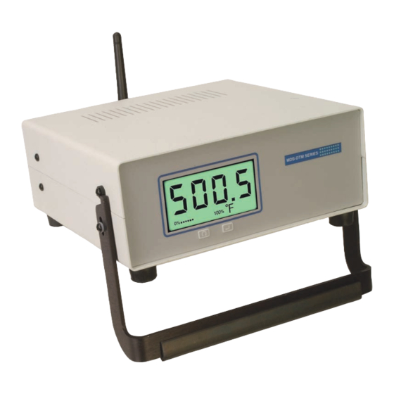
1.3 General Description OMEGA’s new MDS-DTM-RTD Series Benchtop Meter has the functions of a digital temperature meter, enclosed in a benchtop case. It is ideal for laboratory use and applications requiring portable temperature measurement. There is one basic model, a single-channel unit that features a terminal, M8, or M12 input that is configured for use with a RTD signal. - Page 9 Introduction Omega offers six different versions of the MDS-DTM-RTD Series Benchtop Meter. Table 1: MDS-DTM-RTD Series Benchtop Meter Versions Version Terminal M8 Connector M12 Connector nalog larm Wireless Input Input Output Output MDS-DTM-RTD MDS-DTM-RTD-W MDS-DTM-RTD-M8 MDS-DTM-RTD-M8-W MDS-DTM-RTD-M12 MDS-DTM-RTD-M12-W www.DataSheet.net/ Datasheet pdf - http://www.DataSheet4U.co.kr/...
-
Page 10: Section 2 - Hardware
Customer Service Department at 1-800-622-2378 or 203-359-1660. We can also be reached on the Internet at www.omega.com, e-mail: cservice@omega.com. When you receive the shipment, inspect the container and equipment for any signs of damage. Note any evidence of rough handling in transit. -
Page 11: Battery Connection
Hardware NOTE: ll electrical connections and wiring should be performed by suitably trained personnel only. 2.3.3 Battery Connection Your benchtop meter will also operate on 2 D cell Alkaline batteries. Follow instructions in section 3.9 for details on how to replace the batteries. www.DataSheet.net/ Datasheet pdf - http://www.DataSheet4U.co.kr/... -
Page 12: Section 3 - Installation And Wiring
Installation, Mounting & Wiring Section 3 – Installation & Wiring 3.1 General Meter Dimensions (8.13) DIMENSIONS mm (in) www.DataSheet.net/ (3.13) (3.68) Figure 3-1. General Meter Dimensions Datasheet pdf - http://www.DataSheet4U.co.kr/... -
Page 13: Front Panel With Overlay
MIN MAX AVG PEAKCALBAT HAL LAL LOGSET TX °F 100% Figure 3-2. Front Panel Controls, Indicators www.DataSheet.net/ 3.3 Rear Panel (Terminal Input, nalog Output, larm Output, Wireless) OMEGA ENGINEERING, INC. www.omega.com e-mail: info@omega.com STAMFORD, CT. 06907-0047 INPUT WIRELESS ANTENNA ANALOG OUTPUT FUSE: F1A, 250V BATTERY: 2x D-CELL, 1.8 Vdc MAX... -
Page 14: Rear Panel (M8 Input, Analog Output, Alarm Output, Wireless)
Installation, Mounting & Wiring 3.4 Rear Panel (M8 Input, nalog Output, larm Output, Wireless) OMEGA ENGINEERING, INC. www.omega.com INPUT e-mail: info@omega.com STAMFORD, CT. 06907-0047 WIRELESS ANTENNA ANALOG OUTPUT FUSE: F1A, 250V BATTERY: 2x D-CELL, 1.8 Vdc MAX CAUTION: DISPOSE OF BATTERY PROPERLY... -
Page 15: Rear Panel (Terminal Input, Analog Output, Alarm Output)
Installation, Mounting & Wiring 3.6 Rear Panel (Terminal Input, nalog Output, larm Output) www.omega.com OMEGA ENGINEERING, INC. e-mail: info@omega.com STAMFORD, CT. 06907-0047 INPUT ANTENNA ANALOG OUTPUT FUSE: F1A, 250V BATTERY: 2x D-CELL, 1.8 Vdc MAX CAUTION: DISPOSE OF BATTERY PROPERLY... -
Page 16: Rear Panel (M12 Input, Analog Output, Alarm Output)
Installation, Mounting & Wiring 3.8 Rear Panel (M12 Input, nalog Output, larm Output) OMEGA ENGINEERING, INC. www.omega.com INPUT e-mail: info@omega.com STAMFORD, CT. 06907-0047 ANTENNA ANALOG OUTPUT FUSE: F1A, 250V BATTERY: 2x D-CELL, 1.8 Vdc MAX CAUTION: DISPOSE OF BATTERY PROPERLY... -
Page 17: Installing Wireless Antenna
Installation, Mounting & Wiring • Do not connect the positive terminal and negative terminal of the battery to each other with any metal object (such as wire). • Do not carry or store the battery together with metal objects. • Do not pierce the battery with nails, strike the battery with a hammer, step on the battery or otherwise subject it to strong impacts or shocks. -
Page 18: Wiring (Sensor, Analog Output, Alarm Output)
Installation, Mounting & Wiring 3.11 Wiring (Sensor, nalog Output, larm Output) Temperature Sensor Model MDS-DTM-RTD is designed to operate with a 3-wire, PT100 external sensor or integral probe assembly. Wires are connected to TB1 located on the rear panel. BLACK WIRES RED WIRE PT100 SENSOR... - Page 19 Installation, Mounting & Wiring Analog Output Wiring Example CHART RECORDER – SHIELD WIRE ENCLOSURE GROUND Figure 3-14. Wiring - Analog Output Alarm Wiring Example Driving a relay or low impedance input (Open Drain) * 1N4004 DIODE www.DataSheet.net/ 24 VDC – –...
-
Page 20: Section 4 - Setup & Configuration
Setup & Configuration Section 4 – Setup & Configuration 4.1 Getting Started This section outlines how to setup and configure your MDS-DTM-RTD Benchtop Meter before installation and use. All configuration settings are set and saved into your meter by connecting the included USB programming cable and running the software utility that was included with your unit on your computer. - Page 21 From this screen you select the folder were you want the program files installed on your PC. The default setting will install the software under your “Program” folders in a new folder named “Omega” To continue with installing the program click the “Next >” button.
- Page 22 Setup & Configuration Figure 4-4. Software - License Agreement Screen From this screen you must select “Agree” to continue installing your program. After making your selection click the “Next >” button. The setup wizard will now complete the process and install the software. www.DataSheet.net/ Figure 4-5.
-
Page 23: Configuration
Setup & Configuration 4.4 Configuration Connecting your meter to your computer A USB Programming cable was included with your unit. This cable is only used during the setup and configuration of your meter. NOTE: This cable does not remain connected during normal use. Figure 4-6. - Page 24 Setup & Configuration Setting Up Your Meter Now that you have connected your USB cable to your PC and to your meter, you can now complete the following steps to configure your meter before placing the unit into operation. You will be using the configuration software utility that you installed onto your PC.
- Page 25 Setup & Configuration Figure 4-10. Utility Program - Connect To Digital Gauge Screen If you have not already connected your meter to a USB port on your PC you must do this now before continuing. After your unit has been connected click the “Next >”...
- Page 26 Setup & Configuration Figure 4-12. Utility Program - Establish Link Screen After successful communication between your connector/transmitter has been established you can click the “Next >” button to proceed and continue setting up your connector/transmitter. If you did not receive this confirmation of proper communication you should click the “Back”...
- Page 27 Setup & Configuration Figure 4-13. Utility Program - Choose Options Screen From this screen you will select the main operating settings for your end device. NOTE: www.DataSheet.net/ Each end device must have a different address number for proper operation. After making your selections click the “Next >” button to proceed and program your settings into your unit.
- Page 28 Setup & Configuration Battery Power Here you can set the amount of time you want the backlighting to stay on when activated and the unit is running on battery power only. NOTE: You can not set the backlighting to be “ lways On” when the unit is powered by battery power.
- Page 29 Setup & Configuration Rising & Falling - The alarm output activates when either the temperature meets or exceeds the High Setpoint OR the temperature falls below the Low Setpoint HAL (High Alarm Limit) Setpoint Set here the high value you want the alarm to activate at. HAL (High Alarm Limit) Deadband Deadband is an area where no action occurs.
- Page 30 Setup & Configuration Scaling Here you can scale the analog output to correspond to the process reading value. 4-20 mA Example: This table shows analog output values you should expect if you set 4mA = 0°F and 20mA = 1000°F Process Reading nalog Output Value 0°F...
- Page 31 Setup & Configuration Figure 4-15. Calibration Options Screen - Skip Calibration Option From this screen you will select a Calibration option. If the unit does not require calibration you should leave the default selected “Skip Calibration” and continue by clicking the “Next >” www.DataSheet.net/ Figure 4-16.
- Page 32 Setup & Configuration Figure 4-17. Send Settings To Digital Gauge Screen - Finish Option After your meter has been programmed click the “Finish” button to close the utility program. www.DataSheet.net/ 4-13 Datasheet pdf - http://www.DataSheet4U.co.kr/...
-
Page 33: Section 5 - Display Features & Meter Operation
Display Features & Meter Operation Section 5 – Display Features & Meter Operation 5.1 Display Features MIN MAX AVG PEAKCALBAT HAL LAL LOGSET TX °F 100% Figure 5-1. Display Features (1) Process Reading, (2) Units, (3) Bargraph, (4) Status Icons 5.2 Keypad Operation www.DataSheet.net/ MIN MAX AVG PEAK CAL BAT HAL LAL LOG SET TX... -
Page 34: Button Operation
Display Features & Meter Operation 5.3 Button Operation The “MODE” and “SET” buttons located of on the front display of your meter are activated by pushing down onto the keypad button symbol on the front meter label. Mode Button Operation – To activate the “MODE” button, push your finger down on the “MODE”... - Page 35 Display Features & Meter Operation MENU MODE Apply Force 3 Seconds Then Remove MODE 100% MIN VALUE MIN VALUE Apply Force Apply Force Then Remove Then Remove MIN, MAX AND AVG ALL SET TO VALUE OF CURRENT READING 100% 100% MAX VALUE MAX VALUE Apply Force...
- Page 36 Display Features & Meter Operation Continued from previous page UNITS UNITS Apply Force Apply Force Then Remove Then Remove UNIT 100% 100% Apply Force Then Remove UNITS 100% Apply Force Then Remove www.DataSheet.net/ UNITS UNITS Apply Force Then Remove 100% 100% EXIT MODE Force 3...
- Page 37 Display Features & Meter Operation Backlighting Operation The front keypad “Set” Button can be used to activate the backlighting feature. When activated, the backlighting will remain on for the period of time you selected during the setup and configuration in Section 3. Apply Force 3 Seconds To Activate Backlight...
-
Page 38: Section 6 - Optional Wireless Transmitter Operation
Optional Wireless Transmitter Operation Section 6 – Optional Wireless Transmitter Operation 6.1 Introduction Compared to a wired connection, a wireless meter provides much simpler installation. Based on the physical principle of the propagation of radio waves, certain basic conditions should be observed. The following simple recommendations are provided to ensure proper installation and correct operation of your wireless meter. - Page 39 Environment Omega’s wireless end devices and receiver units have been designed to be fixed mounted and operated in a clean and dry indoor environment. Care should be taken to prevent the components of your wireless system from being exposed to moisture, toxic chemicals and extreme cold or hot temperature that are outside the specifications listed in this manual.
-
Page 40: Transmit Rate Vs. Battery Life
Optional Wireless Transmitter Operation • Never use your wireless end device or receiver in medical, nuclear or other dangerous applications where an interruption of readings can cause damage or harm. • Never operate your end device or receiver with any other battery or power source than what’s specified in this manual or on the battery compartment label. - Page 41 Optional Wireless Transmitter Operation 6.4.1 MDS-DTM-RTD Wireless Model - Battery Life Table 2: MDS-DTM-RTD - Wireless Model - Estimated Battery Life Batteries: D Cell lkaline Battery 21 h Capacity nalog Seconds/ Sample Seconds per Wireless Transmission: Weeks Weeks Weeks Weeks 69.5 106.8 111.3...
-
Page 42: Wireless Transmitter Setup
Optional Wireless Transmitter Operation 6.5 Wireless Transmitter Setup After connecting the USB cable and running the configuration software as outlined in Section 3, you will complete the following steps to configure your wireless transmitter before placing the unit into operation. You will be using the configuration software utility that you installed onto your PC in Section 3. - Page 43 Optional Wireless Transmitter Operation Sample Rate This will program your device to transmit 1 data reading to your receiver at a specified time interval. Available settings are 2, 3, 4, 5, 10, 15, 20, 25, 30, 45, 60, 75, 90, 105 or 120 seconds. www.DataSheet.net/ Datasheet pdf - http://www.DataSheet4U.co.kr/...
- Page 44 Optional Wireless Transmitter Operation NOTES: www.DataSheet.net/ Datasheet pdf - http://www.DataSheet4U.co.kr/...
-
Page 45: Section 7 - Maintenance
Section 7 – Maintenance 7.1 Calibration Your MDS-DTM-RTD Series Benchtop Meter has been built, tested, and factory calibrated to meet or exceed the specifications listed here in this manual. Information is provided below on how to have your unit returned for service. -
Page 46: Section 8 - Specifications
Specifications Section 8 – Specifications 8.1 General Range: -51 to 538°C (-60 to 1000°F) Accuracy: ±0.2°C (±0.3°F) or ±0.1% of reading, Whatever greater Resolution: 0.1°C (0.1°F) Operating Environment: -40 to 70°C (-40 to 158°F); 5 to 100% RH non- condensing RTD Probe/ Sensor Input: Pt100, 3-wire Display Type: LCD with selectable backlight... -
Page 47: Wireless Option
Specifications 8.2 Wireless Option Transmit Sample Rate: User programmable from 1 sample/2 min to 1 sample/every 2 sec Radio Frequency (RF) Transceiver Carrier: ISM 2.4 GHz RF Output Power: 10 dBm (10 mW) Range of RF Link: Outdoor Line of Sight: Up to 120 m (400 ft) Indoor/ Urban: Up to 40 m (130 ft) Software... -
Page 48: Pprovals, Regulatory Compliance
pproval, Regulatory Compliance Section 9 – pprovals, Regulatory Compliance NOTE: ll approvals outlined in this manual are based on testing that was done with antennas that are supplied with your meter. Removing and or installing a different antenna will void the product compliance demonstrated in these documents. - Page 49 W RR NTY/DISCL IMER OMEG ENGINEERING, INC. warrants this unit to be free of defects in materials and workmanship for a period of 25 months from date of purchase. OMEG ’s W RR NTY adds an additional one (1) month grace period to the normal two (2) year product warranty to cover handling and shipping time.
- Page 50 Where Do I Find Everything I Need for Process Measurement and Control? OMEG …Of Course! Shop online at omega.com TEMPER TURE Thermocouple, RTD & Thermistor Probes, Connectors, Panels & Assemblies Wire: Thermocouple, RTD & Thermistor Calibrators & Ice Point References Recorders, Controllers &...
Need help?
Do you have a question about the MDS-DTM-RTD Series and is the answer not in the manual?
Questions and answers