Table of Contents
Advertisement
Quick Links
Advertisement
Table of Contents

Related Manuals for Heyuan Intelligence HYFW


Summary of Contents for Heyuan Intelligence HYFW
- Page 1 HYFW Energy Meter User Manual (V2.0) Heyuan Intelligence Technology Co., Ltd...
- Page 2 IMPORTANT DECLARATIONS Copyright © 2020 Heyuan Intelligence Technology Co., Ltd All Rights Reserved This manual may not be reproduced, copied, transmitted or transcribed in whole or in part by any means without the expressed written permission of Heyuan. Any shall be investigated for legal responsibility in violation of copyright or other intellectual property rights of the Company.
-
Page 3: Table Of Contents
Contents Chapter 1 Meter Overview …………………………………………………………………………..1 Chapter 2 Specifications ………………………………………………………………………………….1 Chapter 3 Dimensions & Installation …….…………………………………………………….……….2 Chapter 4 Terminals ………………………………………………………………………...……….…….3 Chapter 5 Typical Wiring ………………………………………………………………………………….3 Chapter 6 Buttons & Display Interfaces ……………………………………………………….……..6 Chapter 7 Indicators ……………………………………….…….…….…….…….….……..…………..13 Chapter 8 After-sales Service …………………………………………………………………...……14 Chapter 9 Contact Us ………………………………………………………………..………..……..14... -
Page 4: Chapter 1 Meter Overview
Chapter 1 Meter Overview HYFW is an advanced, smart DIN rail energy meter. It is widely used in energy distribution sites, energy management systems and intelligent on-line monitoring systems of different industries. Function: Measuring Electric Parameters: three-phase voltage, three-line voltage, three-phase current, zero-sequence current, active power,... -
Page 5: Chapter 3 Dimensions & Installation
Temperature: ±1℃ Power Factor: 1% 2.6 Power Supply Power Supply: AC85~265V(45~65HZ) Power Consumption: <5W 2.9 Working Condition Operating Temperature: -20℃~+70℃ Storage Temperature: -40℃~+75℃ Relative Humidity: 5%~95%(non-condensing) Chapter 3 Dimensions & Installation 3.1 Overall Dimension (unit: mm) Model No. Dimension(mm) HYFW 58.5... -
Page 6: Chapter 4 Terminals
3.2 Installation Method Installation Environment: HYFW should be installed in a dry and dust free environment. Avoid exposing meter to excessive heat, radiation and high electrical noise sources. Install Method: DIN rail Mounting (35mm) Chapter 4 Terminals Upper Row of Terminals... - Page 7 3P4W(CT&PT connection) 3P3W(CT connection no PT) 3P3W(CT&PT connection)
- Page 8 N/- L/+ Current Terminals Installation HYFW current terminal adopts pluggable lock connector, which is convenient for the installation. When installing, insert the terminal head connector into the terminal seat at a 60° angle, and then force it into the terminal seat. When it needs to be pulled out, use a flat-blade screwdriver (spindle diameter of 3mm) to insert into the gap of the terminal base, and pull the terminal head connector out.
-
Page 9: Chapter 6 Buttons & Display Interfaces
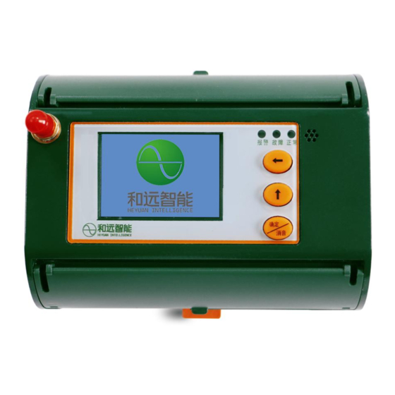
Chapter 6 Buttons & Display Interfaces 6.1 Parameter Inquiry Parameter Inquiry Button ← cycle display of each energy value cycle display of power, power factor, frequency ↑ 确定 Confirm/ Short press:voltage(L-L,L-N) ,current, 消音 Mute leakage,temperature, DI, DO etc Long press:eliminate alarm sound ↑... - Page 10 A. Press the button "确定 Confirm/消音 Mute" to cyclically display interfaces of phase voltage, line voltage, current, leakage, temperature. Voltage(L-N) Voltage(L-L) Current Leakage Temperature Digital Input Phase Sequence Relay Zero Sequence Load properties B. Press button " " to cyclically display interfaces of total power, active power, reactive power, ↑...
- Page 11 Total Power Active Power Reactive Power Apparent Power Power Factor Frequency C. Press buttons " " to cyclically display interfaces of active energy, reactive energy, export reactive energy. Active Energy Reactive Energy Four-Quadrant Energy Import Import Export Export Total Total Net Value Net Value Press the buttons "↑"...
- Page 12 Harmonic of Ua Harmonic of Ub Harmonic of Uc Harmonic of Ia Harmonic of Ib Harmonic of Ic E. Press the buttons " " and " " simultaneously to enter the system self-check mode: ↑ whether the indicator light, buzzer and LCD display are normal 2) Parameter Setting A.
- Page 13 Communication(RS485 parameters) Address setting range: 1~247 Parity Bit:8n1, 8o1, 8e1 Baud Rate Setting Range: 1200,2400,4800,9600 Address Parity Bit Baud Rate Sensor Setting Wiring Mode: 3P4W, 3P3W PT Ratio: 1~9999 CT Ratio:5A、30A、80A、150A、200A、250A、400A、600A、800A、1000A、1500A、2000A、 3000A are optional. The default is 150A or 5A. If the CT is 5A type, we also need to set the CT ratio in the red in the sensor setting interface.
- Page 14 Limit Value: upper/ultimate upper limit for voltage, current, leakage, temperature; lower/ultimate lower limit for voltage, current, leakage, temperature; Ultimate Upper Limit of Voltage Upper Limit of Voltage Lower Limit of Voltage Ultimate Upper Limit of Current Upper Limit of Current Ultimate Upper Limit of Leakage Upper Limit of Leakage Ultimate Upper Limit of Temperature Upper Limit of Temperature...
- Page 15 Ultimate Upper Limit of Over Load Upper Limit of Over Load Ultimate Upper Limit of Voltage Unbalance Upper Limit of Voltage Unbalance Ultimate Upper Limit of Current Unbalance Upper Limit of Current Unbalance Rated Voltage: can be set as 220/380V(low voltage), 57.7/100V(high voltage) Relay Setting It can be correlated voltage, current, leakage, temperature, and it can be correlated one parameter or multiple at the same time.
-
Page 16: Chapter 7 Indicators
Wireless Communication Parameter Setting The wireless version: 2G/4G/NB/LoRa LoRa Version Parameters: Channel, Speed, Power Channel Speed Power Other It refers to select the leakage value mode, full wave leakage &fundamental leakage are optional, the default is full wave leakage. Chapter 7 Indicators Name Colour Description... -
Page 17: Chapter 8 After-Sales Service
Chapter 8 After-sales Service Product Warranty 1. The product warranty period is one year. 2. The company is responsible for free maintenance or exchange within one-year warranty period. 3. The cost of the components and freight shall be charged for improper meter installation and/or operation.
Need help?
Do you have a question about the HYFW and is the answer not in the manual?
Questions and answers