
Related Manuals for Heyuan Intelligence DZS400


Summary of Contents for Heyuan Intelligence DZS400
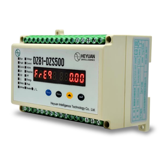
- Page 1 DZ81-DZS500 Smart Three Phase Meter User Manual (V2.0) Heyuan Intelligence Technology Co., Ltd...
- Page 2 IMPORTANT DECLARATIONS Copyright © 2018 Heyuan Intelligence Technology Co., Ltd All Rights Reserved This manual may not be reproduced, copied, transmitted or transcribed in whole or in part by any means without the expressed written permission of Heyuan. Any shall be investigated for legal responsibility in violation of copyright or other intellectual property rights of the Company.
-
Page 3: Table Of Contents
Contents Chapter 1 Meter Overview………………………………………………………………………….1 Chapter 2 Specifications……………………………………………………………………………1 2.1 Input Voltage ………………………………………………………………....1 2.2 Input Current …………………………………………………………………………..1 2.3 Energy …………………………………………………………………………………..1 2.4 Frequency Measurement …………………………………………………………….1 2.5 Measuring Accuracy ……………………………………………………………. …..1 2.6 Communication ………………………………………………………………………..1 2.7 Power Supply ………………………………………………………………………….1 2.8 Working Condition …………………………………………………………………….1 2.9 Pulse Output of Imported Active Energy ………………………………………….2 Chapter 3 Installation and Typical Wiring ……………………………………………………..2 3.1 Dimension (unit: mm) and Comparison Table of Digital Letters Displayed ….2 3.2 Installation Method ……………………………………………………………………2... -
Page 4: Chapter 1 Meter Overview
Chapter 1 Meter Overview DZ81-DZS500 is an advanced, smart networked electricity energy meter. It is widely used in power distribution sites, energy management systems and intelligent monitoring systems of different industries. It measures electric parameters i.e. three -phase/line voltage, three- phase current, zero-sequence voltage, zero-sequence current, voltage unbalance, current unbalance, active power, reactive power, power factor, frequency, load property, 2~31 harmonic analysis, active energy, reactive energy and multi-tariff energy etc. -
Page 5: Chapter 3 Installation And Typical Wiring
Pulse Constant Pulse Width Max. Current Working Voltage 2000imp/kWh 50±2ms 10mA(DC) 5V~24V 2.9 Working Condition Operating Temperature: -20℃~+65℃ Storage Temperature: -40℃~+85℃ Relative Humidity: 20%~90%(non-condensing) Chapter 3 Dimension and Installation 3.1 Dimension (unit: mm) Front View Side View 3.2 Installation Method Installation Environment: DZS500 should be installed in a dry and dust free environment. - Page 6 Terminal Terminal Description Remark Protect Normally Closed DO NC1 COM K1 Protect Normally Open NO1 contact capacity 10A/250VAC Normally Closed DO NC2 COM K2 Normally Open DO NO2 4.3 Energy Pulse Output Status Terminal No. Terminal Description Remark Active Energy Pulse Output P+ null Active Energy Pulse Output P- 4.4 Upper Row of Terminals...
- Page 7 Voltage Input VC Neutral Line Input VN Meter Power Input L/+ power supply: Meter Power Input N/- AC 85V~265V / DC 85~300V Terminal Original Terminal Description Remark Status DI COM DI 1 passive dry contact, internal power supply (DC24V) DI 2 DI 3 Null Protect Normally Closed DO...
-
Page 8: Chapter 5 Typical Wiring
Chapter 5 Typical Wiring... -
Page 9: Chapter 6 Meter Display And Operation
Chapter 6 Meter Display and Operation Interface, Start-up Interface This interface displays the present meter address, communication baud rate, software version number when power up and reset. It will enter next interface automatically 3 seconds later. Interface, Phase A Current IA Interface Press buttons “▲”... - Page 10 Interface, Current Imbalance Interface Press buttons “▲” or “Menu” to check other parameters. Press button “▲”, it will enter 2 interface. Press button “Menu”, it will enter 8 interface. Interface, Phase Voltage Ua Interface Press buttons “▲” or “Menu” to check other parameters. Press button “▲”, it will enter 9 interface.
- Page 11 Interface, Line Voltage Uca Interface Press buttons “▲” or “Menu” to check other parameters. Press button “▲”, it will enter interface. Press button “Menu”, it will enter 16 interface. Interface, Zero-sequence Voltage 3U0 Interface Press buttons “▲” or “Menu” to check other parameters. Press button “▲”, it will enter interface.
- Page 12 Interface, Average Active Power Interface Press buttons “▲” or “Menu” to check other parameters. Press button “▲”, it will enter interface. Press button “Menu”, it will enter 28 interface. Interface, Phase A Reactive Power Interface Press buttons “▲” or “Menu” to check other parameters. Press button “▲”, it will enter interface.
- Page 13 Interface, Phase B Power Factor Interface Press buttons “▲” or “Menu” to check other parameters. Press button “▲”, it will enter interface. Press button “Menu”, it will enter 28 interface. Interface, Phase C Power Factor Interface Press buttons “▲” or “Menu” to check other parameters. Press button “▲”, it will enter interface.
- Page 14 Press buttons “▲” or “Menu” to check other parameters. Press button “▲”, it will enter interface. Press button “Menu”, it will enter 32 interface. Interface, Interface of Export Active Energy in Sharp Period 运行 电压 故障 电流 通讯 有功 无功 功因...
- Page 15 “Menu”, it will enter 36 interface. Interface, Present Time Interface The present interface displays hour, minute, second, year, month, day from left to right. Press buttons “▲” or “Menu” to check other parameters. Press button “▲”, it will switch time interface. Press button “Menu”, it will enter 2 interface.
- Page 16 Communication baud rate in same communication network segment should be the same. User should set communication baud rate according to conditions on sites and communication distance. Communication baud rates can be set as follows (unit: bps) by press button “▲”. Interface Display 2400...
- Page 17 Press button “▲” to set pulse output time of relay. When setting time as “0”, the default DO is level mode. After completing modification, press button “ ” and it will enter 45 interface. Interface, Energy Pulse Interface It displays energy pulse values which each active energy kWh and reactive energy kvarh corresponds to separately.
- Page 18 completing modification, press button “ ” and it will enter 50 interface. Interface, Pulse Output Mode Interface “0” refers to the energy pulse output mode as active energy. “1” refers to the energy pulse output mode as reactive energy. After completing modification, press button “ ”...
- Page 19 interface. Interface, Interface of Decimal Digits of Current The present interface displays the decimal digits of current as 1. Press button “▲” to set decimal digits. After completing modification, press button “ ” and it will enter 56 interface. Interface, Power Range Interface The present interface displays the unit of power as kW and maximum power is 9.999kW.
- Page 20 Interface, The Proportion of Starting Current to Rated Current Interface The setting range for the proportion is 10%~50%. Press button “▲” to set the proportion. After completing modification, press button “ ” and it will enter 61 interface. Interface, Start-up Time Interface The setting range is 1~250s.
- Page 21 Press button “▲” to set as alarm, as tripping and as invalid. The setting value range is [105%~200%]Ue, action time 0.1s~25.0s and setting difference 0.1s. The present interface displays the over-voltage protection setting as tripping. When voltage of any phase is more than 130% of rated voltage, delay 5s to trip. After completing modification, press button “...
- Page 22 Press button “▲” to set as alarm, as tripping and as invalid. The setting value range is [30%~100%]Ie, action time 0.1s~25.0s and setting difference 0.1s. The present interface displays the over-current protection setting as tripping. When zero-sequence current is more than 80% of rated current, delay 5s to trip. After completing modification, press button “...
-
Page 23: Chapter 7 After-Sales Service
Press button “ ” for long and enter password again. Press button “Menu” to display the interfaces as follows: Interface, Parameter Group 5 Interface Press button “ ” to enter parameter group 5 and then enter 74 interface. Interface, SOE Query Interface The present interface displays causes and time of event-1. -
Page 24: Chapter 12 Contact Us
3. Except statutory holidays and force majeure. Chapter 8 Contact Us Headquarter Add.: 7F No.1 Aosheng Building, 1166 Xinluo Street, High-tech Development Zone, Jinan, P.R. China 250101 Factory Add.: 2F Innovation Factory, Feiyue Road, High -tech Development Zone, Jinan, P.R. China 250101 Tel: +86 68621770-863 Code: 250101 E-mail: info@heyuanintel.com...
Need help?
Do you have a question about the DZS400 and is the answer not in the manual?
Questions and answers