
Related Manuals for Heyuan Intelligence DZ81-DZS300


Summary of Contents for Heyuan Intelligence DZ81-DZS300
- Page 1 DZ81-DZS300 Energy Meter User Manual (V2.0.4) Heyuan Intelligence Technology Co., Ltd...
- Page 2 IMPORTANT DECLARATIONS Copyright © 2018 Heyuan Intelligence Technology Co., Ltd All Rights Reserved This manual may not be reproduced, copied, transmitted or transcribed in whole or in part by any means without the expressed written permission of Heyuan. Any shall be investigated for legal responsibility in violation of copyright or other intellectual property rights of the Company.
-
Page 3: Table Of Contents
Contents Chapter 1 Meter Overview ……………………………………………………………………………..1 Chapter 2 Specifications ………………………………………………………………………………….1 Chapter 3 Dimensions & Installation …….…………………………………………………….…….2 Chapter 4 Terminals ………………………………………………………………………...……….…….2 Chapter 5 Typical Wiring ………………………………………………………………………………….3 Chapter 6 Parameters Display Interfaces ……………………………………………………….…..4 Chapter 7 Parameters Setting Interface ……………………………………….…….……..…………..7 Chapter 8 Basically Measured Parameters Zone (Modbus Protocol) ………………....10 Chapter 9 Basic Set Parameters Zone (Modbus Protocol) ……………………….…………….….11 Chapter 10 Measurement Parameters (Modbus Protocol) ………………….……………..….…...12 Chapter 11 After-sales Service …………………………………………………………………...…….14... -
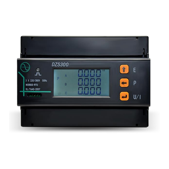
Page 4: Chapter 1 Meter Overview
Frequency: ±0.01Hz 2.6 Communication RS485/Modbus-RTU Communication Protocol Baud Rate: 1200~9600bps (settable) Remark: DZ81-DZS300 adopts RS485 interfaces and Modbus RTU communication protocol to communicate. The terminals are 485A and 485B. The RS485 transmission medium is shielded twisted pair. 2.7 Power Supply Power Supply: AC85~265V(45~55HZ)/ DC85~300V... -
Page 5: Chapter 3 Dimensions & Installation
Top View (Unit: MM) Side View (Unit: MM) Model No. Dimension(mm) DZ81-DZS300 3.2 Installation Method Installation Environment: DZS300 should be installed in a dry and dust free environment. Avoid exposing meter to excessive heat, radiation and high electrical noise sources. -
Page 6: Chapter 5 Typical Wiring
Chapter 5 Typical Wiring 5.1 Wiring Approach 1 5.2 Wiring Approach 2... -
Page 7: Chapter 6 Parameters Display Interfaces
5.3 Interface of Energy Pulse Output 5.4 RS485 Interface 5.5 PPS Output Interface 485A 485B Chapter 6 Parameters Display Interfaces 6.1 Interfaces of Voltage, Current and Date Press button " " to cyclically display interfaces of voltage, current and date. 6.2 Interface of Energy Press the button "... - Page 8 6.4 Interface of Harmonics Press the buttons " " and " " simultaneously to enter harmonics display interfaces. Press buttons " " to cyclically display interfaces of total voltage harmonic content, total current harmonic content, total voltage odd harmonic content, total voltage even harmonic content, total current odd harmonic content, total current even harmonic content, voltage 2 harmonic content, current 2 harmonic content.
- Page 9 6.5 Interface of Historical Multi-tariff Press the buttons " " and " " simultaneously to enter multi-tariff display interface. Press the button " " to cyclically display energy of N months (N referring to 0~11, 0 signifying present month). Press button " "...
-
Page 10: Chapter 7 Parameters Setting Interface
Chapter 7 Parameter Setting Interface DZS300 On measured value display interface, press buttons the " " and " " at the same time, it will enter total parameters setting mode. Under setting mode, the button " " will be used for digital shift. It can edit 1 digit shift left each time, and the digit will flash. - Page 11 7.1 Password Setting Interface Press buttons " " and " " at the same time, it will enter total parameters setting mode. Enter password setting interface, the default password is 0001. If the password is not correct, press button " "(U/I).
- Page 12 7.6 Voltage Ratio Setting Interface Enter voltage ratio setting interface, the present voltage ratio is 0001. Voltage ratio setting should comply with the requirements of register table. Press the buttons " " and " " to set the range of voltage ratio among 1-9999. After completing setting, press button "...
-
Page 13: Chapter 8 Basically Measured Parameters Zone (Modbus Protocol)
Enter setting interface of backlight time. The present interface displays the backlight time is 10s (100ms as a unit). Press the button " " and " " to set the backlight time among 10~600(i.e. 1s to 60s). After completing setting, press button " "... -
Page 14: Chapter 9 Basic Set Parameters Zone (Modbus Protocol)
4099 1003 reserved 0xffff 0~65535 4100 1004 reserved 0xffff 0~65535 4101 1005 line voltage(A-B) Magnifying 100 times 0~65535 4102 1006 line voltage(B-C) Magnifying 100 times 0~65535 4103 1007 line voltage(C-A) Magnifying 100 times 0~65535 4104 1008 reserved 0xffff 0~65535 4105 1009 0~65535 phase/line current of phase A... -
Page 15: Chapter 10 Measurement Parameters (Modbus Protocol)
Address Address Default Parameter Name Value Range Value High : 0:(N,8,1) , 1:(o,8,1) , 8194 2002 RS485 serial port parameter 2:(e,8,1) 8195 2003 RS485 serial port parameter 0:1200, 1:2400, 2:4800, 3:9600, 8196 2004 Voltage connection mode 0:3LN,1:2LL 8197 2005 1∼9999 (Remark 1) 8198 2006 1~9999 (Remark 1) - Page 16 12805 3205 Second 0-59 12806 3206 Millisecond 0-999 Remark: 1. Write register to set time, read register to read time of the meter. In order to prevent the occurrence of February 31st, the "Time" must be set by the command 10H, otherwise invalid. The clock chip automatically falls milliseconds to zero.
-
Page 17: Chapter 11 After-Sales Service
Chapter 11 After-sales Service Product Warranty 1. The product warranty period is one year. 2. The company is responsible for free maintenance or exchange within three -year warranty period. 3. The cost of the components and freight shall be charged for improper meter installation and/or operation.
Need help?
Do you have a question about the DZ81-DZS300 and is the answer not in the manual?
Questions and answers