
Related Manuals for Heyuan Intelligence DZ81-MS3UI7E3


Summary of Contents for Heyuan Intelligence DZ81-MS3UI7E3
- Page 1 DZ81-MS3UI7E3 Power Meter User Manual V2.0 Heyuan Intelligence Technology Co., Ltd...
- Page 2 IMPORTANT DECLARATIONS Copyright © 2018 Heyuan Intelligence Technology Co., Ltd All Rights Reserved This manual may not be reproduced, copied, transmitted or transcribed in whole or in part by any means without the expressed written permission of Heyuan. Any shall be investigated for legal responsibility in violation of copyright or other intellectual property rights of the Company.
-
Page 3: Table Of Contents
Contents Chapter 1 Meter Overview………………………………………………………………………………...1 Chapter 2 Specifications…………………………………………………………………………………..1 2.1 Input Voltage ………………………………………………………………......1 2.2 Input Current ………………………………………………………………………………..1 2.3 Frequency Measurement ……………………………………………………………………1 2.4 Accuracy ………………………………………………………………………………………1 2.5 Communication ……………………………………………………………………………….1 2.6 Power Supply …………………………………………………………………………………1 2.7 Working Condition ……………………………………………………………………………2 2.8 Pulse Output ………………………..………………………………………………………...2 2.9 Input Voltage ………………………..………………………………………………………...2 2.10 Input Current ………………………..……………………………………………………….2 Chapter 3 Dimension &... -
Page 4: Chapter 1 Meter Overview
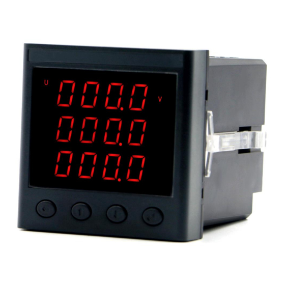
Chapter 1 Meter Overview DZ81-MS3UI7E3 is an advanced, smart networked energy meter. It is widely used in power distribution sites, energy management systems and intelligent monitoring systems of different industries. Measuring all parameters: three phase/line voltage, three phase current, active power, reactive power, power factor, frequency, multi-tariff, total active/reactive energy etc. -
Page 5: Working Condition
Power-line Connection Terminals: L/+ and N/- Remark: Terminals for the power supply are (L/+, N/-). If the quality of power is poor or there is an EMI problem, it’s recommended to equip an EMC filter in the auxiliary power supply loop to increase resistance to interference. 2.7 Working Condition Operating Temperature: -20℃~+70℃... -
Page 6: Chapter 4 Terminals
standard panel of switch cabinet. A. Remove the clips from the meter and insert the meter into the panel from the front side. Make sure that the screen is at the front of the panel. B. Install clips on the back side of the meter and fix tightly to ensure the meter is affixed to the panel. Chapter 4 Terminals 485B 485A... - Page 7 B. Three-Phase Three-Line Wiring Mode in Low Voltage C. Three-Phase Four-Line Wiring Mode in High Voltage Uc Un D. Three-Phase Three-Line Wiring Mode in High Voltage Uc Un...
-
Page 8: Digital Input Wiring
5.2 Digital Input Wiring 5.3 Energy Pulse Wiring Mode 5.4 RS485 Communication Interface 5.5 Power Supply Chapter 6 Meter Display There are four buttons on the front panel, labeled left shift button “ ”, plus button “P”, button “ ”, minus button “... -
Page 9: Chapter 7 Meter Operation
Phase Voltage Line Voltage Current Digital Inputs 6.1.2 Press button “ ”, it will cyclically display the values of energy parameters, including total active energy values and total reactive energy values. In interfaces below, the Ep: 1234567.8kWh, Eq: 1234567.8kVarh. Active Energy Reactive Energy 6.1.3 Press button “... -
Page 10: Parameters Setting Steps
flashing digit is 9, press button " " and the digit will become 0. The button " " is used to minus 1. Press button “ ” each time and the flashing digit minus 1. If the flashing digit is 0, press button " "... - Page 11 Step 2. Press button “ ” to shift digits left. Step 3. Repeat step 1 and step 2 until the last digit. After setting, press button “ ” to confirm and enter baud rate setting interface. 7.2.3 Baud Rate Setting Interface The baud rate can be set as 9600, 4800, 2400 and 1200.
- Page 12 Step 1. Press button “ ” or button “ ” to change voltage wiring mode until choose the needed one. Step 2. After setting, press button “ ” to confirm and enter current wiring mode setting interface. 7.2.6 Current Wiring Mode Setting Interface There are 2 options for the current wiring modes, i.e.
- Page 13 This interface displays the present CT ratio, whose value ranges from 1 to 9999. The setting methods are as follows. Step 1. Press button “ ” or button “ ” to change value of the first digit, which ranges from 0 to 9. Step 2.
-
Page 14: Chapter 8 System Parameters
Chapter 8 System Parameters 8.1 Basically Measured Parameters Zone (Function Code 03 Read) Address Address Value Category Parameter Default (DEC) (HEX) Range magnifying 0~65535 4096 1000 phase A voltage 100 times magnifying 0~65535 4097 1001 phase B voltage 100 times Phase magnifying 0~65535... - Page 15 -32768~ magnifying 4114 1012 reactive power of phase A 1000 times 32767 -32768~ magnifying 4115 1013 reactive power of phase B Reactive 1000 times 32767 -32768~ Power magnifying 4116 1014 reactive power of phase C 1000 times 32767 -32768~ total three-phase reactive magnifying 4117 1015...
-
Page 16: Basically Set Parameters Zone (Function Code 03 Read)
0:1200, 1:2400, 8194 2002 serial port baud rate 2:4800, 3:9600 0:(N,8,1), serial port parity 8195 2003 1:(o,8,1), check 2:(e,8,1) 0:3LN,1: 8196 2004 voltage wiring mode 0:3CT,1: 8197 2005 current wiring mode 8198 2006 1∼9999 8199 2007 1~9999 8200 2008 backlight time(NC) 5~20(0) 8201 2009... -
Page 17: Real-Time Energy Zone (Function Code 03/04 Read)
8.4 Real-time Energy Zone (Function Code 03/04 Read) Address Address Category Parameter Default Value Range (DEC) (HEX) 16384 4000 Total Active 0~99999999.9 16385 4001 Energy Import Active 16386 4002 0~99999999.9 Energy 16387 4003 Export Active 16388 4004 0~99999999.9 Energy 16389 4005 Total Real- 16390... -
Page 18: Chapter 9 After-Sales Service
Chapter 9 After-sales Service Product Warranty 1. The product warranty period is one year. 2. The company is responsible for free maintenance or exchange within one-year warranty period. 3. The cost of the components and freight shall be charged for improper meter installation and/or operation.
Need help?
Do you have a question about the DZ81-MS3UI7E3 and is the answer not in the manual?
Questions and answers