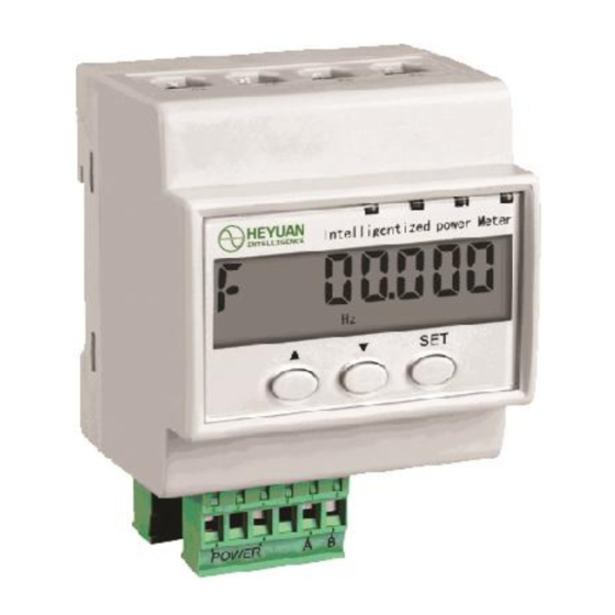
Summary of Contents for Heyuan Intelligence DZS400
- Page 1 3 Phase 4 Wire Multi Circuit Energy Meter DZS400 Heyuan Intelligence Technology Co., Ltd.
- Page 2 IMPORTANT DECLARATIONS Copyright © 2018 Heyuan Intelligence Technology Co., Ltd All Rights Reserved This manual may not be reproduced, copied, transmitted or transcribed in whole or in part by any means without the expressed written permission of Heyuan. Any shall be investigated for legal responsibility in violation of copyright or other intellectual property rights of the Company.
-
Page 3: Table Of Contents
Contents Chapter 1 Meter Overview………………………………………………………….1 Chapter 2 Specifications…………………………………………………………………………1 2.1 Input Voltage ………………………………………………....1 2.2 Input Current …………………………………………………………..1 2.3 Energy …………………………………………………………………..1 2.4 Frequency Measurement …………………………………………….1 2.5 Power Consumption …………………………………………………...1 2.6 Communication ………………………………………………………..1 2.7 Power Supply …………………………………………………………..2 2.8 Working Condition …………………………………………………….2 2.9 Pulse Output of Imported Active Energy ………………………….2 Chapter 3 Installation and Installation …………………………………………..2 3.1 Dimension (unit: mm) ……………... -
Page 4: Chapter 1 Meter Overview
Chapter 1 Meter Overview The DZS400 is an advanced, three phase multi-circuit networked multifunctional energy meter. It is widely used in power distribution sites, energy management systems and intelligent monitoring systems of different industries. It can monitor up to 4* three phase circuits: current, voltage, frequency, active energy, reactive energy, four-quadrant reactive energy etc. -
Page 5: Energy
3×1.5(6)A, 3×10(40)A, 3×20(100)A, 3×50(200)A, 3×100(400)A etc. Note: The meter should be used and incorporated with our special CTs which can be customized 2.3 Energy Accuracy Class: Class 1 2.4 Frequency Measurement Reference Frequency: 50Hz 2.5 Power Consumption: Each phase voltage circuit:≤1.5W、2VA Each phase current circuit:≤1VA 2.6 Communication RS485/Modbus-RTU Communication Protocol... -
Page 6: Installation Method
3.2 Installation Method Installation Environment: DZS400 should be installed in a dry and dust free environment. Avoid exposing meter to excessive heat, radiation and high electrical noise sources. Install Method: DIN rail Mounted. Chapter 4 Terminals... -
Page 7: Chapter 5 Typical Wiring
Terminal Function 1, 2 Power Supply 3, 4 RS485 Communication Interface Phase A Voltage Phase B Voltage Phase C Voltage Neutral Line Voltage Active Pulse Channel of 4 circuits 10, 11, 12, 13 Current Transformer Interface of 1st, 2nd, 3rd, 4th circuit (1~4 circuits optional) Chapter 5 Typical Wiring 5.1 Active pulse channel wiring(sorted from left to right)(terminal pin 9) -
Page 8: Chapter 6 Meter Display And Operation
5.2 Voltage and Current Wiring Diagram Three-phase combined transformer Note : Please pay attention to the direction of the current transformer. ⊙ ⓧ : the current flow in direction : the current outflow direction The arrows are used to indicate the current direction of the transformer arrow direction to be consistent with the load direction Chapter 6 Meter Display &... -
Page 9: Digits And Symbols Display
6.2 Digits and Symbols Display Digits Display Communication Indication Unit Figure 1 LCD Display Interface Reference Diagram Figure 2 Phase B Current of 1st Circuit Figure 3 Active Energy of 4th Circuit 序号 Item LCD 字符 LCD Display 含义 Description 仪表密码... -
Page 10: Display Interface
退出 Return 返回上一级 Back 系统时钟:System Clock 系统时间:System Time 系统日期:System Date ---01---回路字数 Circuit 6.3. Display Interface The meter can circularly display system date/time, three phase voltage, frequency, real-time values of each electrical parameters in each circuit(I, kW, Kvar,cosφ, kWh, kvarh) 6.4 Parameter Setting Interface Password Inquiry Interface Press “SET”... -
Page 11: Chapter 7 After-Sales Service
Press ”▲” to enter the interface. Press “SET” to set Modbus address. The default address is 01. The setting range is 01~FF. After setting, press ”SET” again to confirm. Baud Rate Setting Interface Press ”▲” to enter the interface. Press “SET” to set the parameters. Press ”▲”... -
Page 12: Chapter 8 Contact Us
Chapter 8 Contact Us Headquarter Add.: 7F No.1 Aosheng Building, 1166 Xinluo Street, High-tech Development Zone, Jinan, P.R. China 250101 Factory Add.: 2F Innovation Factory, Feiyue Road, High-tech Development Zone, Jinan, P.R. China 250101 Tel: +86 68621770 Code: 250101 E-mail: info@hyznworld.com...


Need help?
Do you have a question about the DZS400 and is the answer not in the manual?
Questions and answers