
Related Manuals for Kampmann KaCompact KG


Summary of Contents for Kampmann KaCompact KG
- Page 1 KaCompact KG ► Assembly, installation and operating instructions Keep these instructions in a safe place for future use! Issue08/23EN SAP No.1873611...
-
Page 3: Table Of Contents
Table of contents 1 General ..........................5 1.1 About these instructions ........................1.2 Explanation of Symbols.......................... 2 Safety............................ 6 2.1 Correct use............................. 2.2 Limits of operation and use........................2.3 Risk from electrocution!......................... 2.4 Personnel requirements - Qualifications ....................2.5 Personal Protective Equipment ......................3 Transport, storage and packaging.................. - Page 4 7.3 KaControl............................... 29 7.3.1 KaControl connection and wiring conditions ..................... 29 7.4 KaControl MC control ..........................32 7.4.1 KaControl MC connection and wiring conditions ..................32 8 Pre-commissioning checks....................35 9 Operation..........................36 9.1 KaControl............................... 36 9.1.1 Main menu ..............................36 9.1.2 Ventilation overview..........................
-
Page 5: General
KaCompact KG Assembly, installation and operating instructions General About these instructions These instructions ensure the safe and efficient handling of this equipment. These instructions form an integral part of the equipment and have to be kept in the direct vicinity of the equipment and available to personnel at all times. -
Page 6: Safety
KaCompact KG Assembly, installation and operating instructions Safety This section provides an overview of all important safety aspects to ensure optimum protection of personnel as well as safe and trouble-free operation. In addition to the safety instructions in these operating instructions, the valid safety, accident pre- vention and environmental protection regulations must be observed for the area of use of the unit. - Page 7 KaCompact KG Assembly, installation and operating instructions Limits of operation and use Limits of operation Min./max. water temperature °C 4-90 Min./max. air intake temperature °C -16-(+40) Min./max. air humidity 20-90 Min. operating pressure bar/kPa Max. operating pressure bar/kPa 10/1000 Min./max. glycol percentage 0-50 Tab. 1: Limits of operation...
-
Page 8: Risk From Electrocution
KaCompact KG Assembly, installation and operating instructions IMPORTANT NOTE! Danger of frost in cooling mode! There is a risk of the heat exchanger freezing when used in unheated rooms. Make sure that the unit is equipped with a frost protection sensor and/or thermostat in this case. -
Page 9: Personnel Requirements - Qualifications
KaCompact KG Assembly, installation and operating instructions Personnel requirements - Qualifications Expertise The installation of this product requires specialist knowledge of heating, cooling, ventilation, installation and electrical engin- eering. This knowledge, generally learned in professional training in one of the fields mentioned above, is not described sep- arately. -
Page 10: Transport, Storage And Packaging
Submit a complaint to the freight forwarder. IMPORTANT NOTE! Warranty claims can only be made within the applicable period for complaints. (More information is avail- able in the T&Cs on the Kampmann website) IMPORTANT NOTE! Material damage caused by incorrect transport! Units being transported can drop or topple over if transported wrongly. -
Page 11: Storage
KaCompact KG Assembly, installation and operating instructions Storage Store packaging under the following conditions: Do not store outdoors. Store in a dry and dust-free place. Store in a frost-free place. Do not expose to aggressive media. Protect from direct sunlight. -
Page 12: Technical Data
KaCompact KG Assembly, installation and operating instructions Technical data Device KaCompact KG horizontal Size Nominal air volume flow 1500 2500 4000 6000 [m³/h] Length [mm] 1958 2507 2908 3008 Height [mm] 1348 1722 2095 2095 Width [mm] 1291 Outside air sound power... -
Page 13: Construction And Function
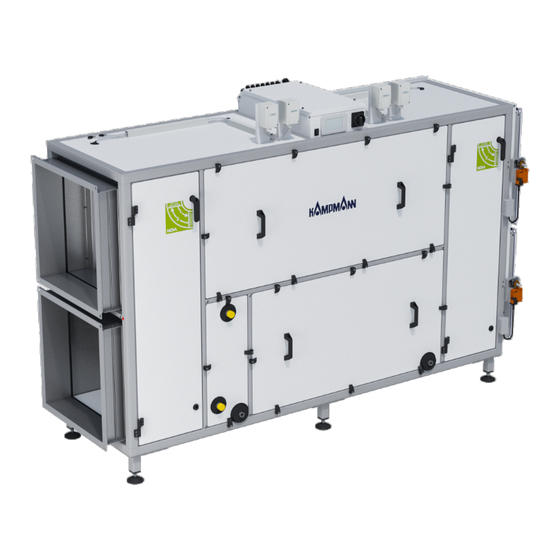
Brief description The KaCompact KG air handling unit is used in standard applications such as catering, hotels, offices and business premises. EC centrifugal fans are used to bring fresh external air into the building and stale outgoing air out of the building. To save en- ergy, the thermal energy of the outgoing air is transferred to the ingoing air by means of a counterflow plate heat exchanger. -
Page 14: Installation And Wiring
KaCompact KG Assembly, installation and operating instructions Installation and wiring Defining the extract air side Horizontal model, extract air on the left Vertical model, extract air on the left Fig. 2: Extract air side on the left Horizontal model, extract air on the right Vertical model, extract air on the right Fig. 3: Extract air side on the right... -
Page 15: Minimum Clearances
KaCompact KG Assembly, installation and operating instructions Minimum clearances Fig. 4: Inspection area horizontal Mounting area Duct system according to dimensions provided by Inspection area for maintenance customer Dimensions inspection area horizontal A [mm] B [mm] 1958 1100 2508 1150 2908... -
Page 16: Installation
KaCompact KG Assembly, installation and operating instructions Installation CAUTION! Risk of injury from sharp metal housing! The inner metal of the casing can have sharp edges. Wear suitable protective gloves. 6.4.1 Setting up the unit Unit as delivered Use an industrial truck to position the unit at the required position. - Page 17 KaCompact KG Assembly, installation and operating instructions Permanently screw the screws into the profile. Use the caps supplied to seal the corners. Remove the yellow protective cap from the condensate drain. Connect the ¾” male condensate drain. Note: Suction-side trap with heat recovery, pressure-side trap with the chiller.
-
Page 18: Installation Of The Duct System
KaCompact KG Assembly, installation and operating instructions 6.4.2 Installation of the duct system Overview of the horizontal connecting frame Size 15, horizontal Size 25, horizontal Size 40, horizontal Size 60, horizontal The dimensions of the connecting frames are identical with units with extract air on the left and extract air on the right. -
Page 19: Installation Of The Horizontal Chiller Module
KaCompact KG Assembly, installation and operating instructions Overview of the vertical connecting frame Size 15, vertical Size 25, vertical Size 40, vertical Size 60, vertical The dimensions of the connecting frame are shown for extract air on the left. The dimensions are correspondingly reversed for extract air on the right. -
Page 20: Connection To The Pipe Network
KaCompact KG Assembly, installation and operating instructions Installation 6.5.1 Connection to the pipe network The supply and return connections are located on the front side of the unit as standard. The piping must be laid in such a way that no mechanical stresses are transferred to the heat exchanger and the accessibility of the unit during maintenance and repair work is not impaired. - Page 21 KaCompact KG Assembly, installation and operating instructions BG 25 horizontal, outgoing air left BG 25 horizontal, outgoing air right BG 40 horizontal, outgoing air left BG 40 horizontal, outgoing air right BG 60 horizontal, outgoing air left BG 60 horizontal, outgoing air right...
- Page 22 KaCompact KG Assembly, installation and operating instructions BG 15 vertical, outgoing air left BG 15 vertical, outgoing air right BG 25 vertical, outgoing air left BG 25 vertical, outgoing air right...
- Page 23 KaCompact KG Assembly, installation and operating instructions BG 40 vertical, outgoing air left BG 40 vertical, outgoing air right BG 60 vertical, outgoing air left BG 60 vertical, outgoing air right Water connections Size Registry Heating/cooling Heating/cooling Heating/cooling Heating/cooling Connection (AG) 1“...
-
Page 24: Overview Of Ball Valves
KaCompact KG Assembly, installation and operating instructions 6.5.2 Overview of ball valves Nominal size Air flow volume [m³/h] Article number DN15. KVS 1.0 0.25 - 0.4 196000050890 DN15. KVS 1.6 0.4 - 0.6 196000050891 DN15. KVS 2.5 0.6 - 1.0 196000050892 DN20. -
Page 25: Electrical Connection
KaCompact KG Assembly, installation and operating instructions Electrical connection Maximum electrical rating values Size Nominal voltage Mains frequency Nominal power Nominal current IP class Protection class [Hz] [kW] 1.30 IP21 2.16 IP21 4.40 IP21 5.80 IP21 Tab. 7: Maximum electrical rating values Electromechanical control 7.2.1 Electromechanical connection and wiring conditions... - Page 26 KaCompact KG Assembly, installation and operating instructions...
- Page 27 KaCompact KG Assembly, installation and operating instructions...
- Page 28 KaCompact KG Assembly, installation and operating instructions...
-
Page 29: Kacontrol
KaCompact KG Assembly, installation and operating instructions KaControl 7.3.1 KaControl connection and wiring conditions In this case, all the components are cabled and the cables are pulled centrally into the electrical connection box. All the actu- ators and sensors are connected to the control electronics in such a way that the I&C technicians only need to connect the... - Page 30 KaCompact KG Assembly, installation and operating instructions...
- Page 31 KaCompact KG Assembly, installation and operating instructions...
-
Page 32: Kacontrol Mc Control
KaCompact KG Assembly, installation and operating instructions KaControl MC control 7.4.1 KaControl MC connection and wiring conditions In this case, all the components are cabled and the cables are pulled centrally into the electrical connection box. All the actu- ators and sensors are connected to the control electronics in such a way that the I&C technicians only need to connect the... - Page 33 KaCompact KG Assembly, installation and operating instructions...
- Page 34 KaCompact KG Assembly, installation and operating instructions...
-
Page 35: Pre-Commissioning Checks
KaCompact KG Assembly, installation and operating instructions Pre-commissioning checks When commissioning the device for the first time, ensure that all the necessary requirements are met so that the device can function safely and in accordance with its intended use. Structural tests Are all the air passages on the ducts and adapters the correct size? Check that the unit is securely standing and fixed. -
Page 36: Operation
Operation KaControl The KaCompact KG is operated by a touch display, which is always positioned centrally at the top of the unit. This user inter- face enables the operator to observe current statuses, enter settings, and read out warnings/faults. 9.1.1 Main menu The main menu features a menu bar at the top of the screen and a rotation menu in the centre. -
Page 37: Temperature Control
KaCompact KG Assembly, installation and operating instructions 9.1.4 Temperature control Depending on the configuration of the system, the setpoints for the temper- atures (room temperature and supply air temperature) can be set in the “Temperature control” sub-menu. They can be displayed as pure supply air temperature control or as room temperature-supply air temperature cascade control. -
Page 38: Settings
KaCompact KG Assembly, installation and operating instructions An active alarm can be rest using the “Acknowledge” key. 9.1.7 Settings The full PGD menu (Emulation) of the AUL outside air control panel and the H2 control panel can also be accessed. -
Page 39: Ventilation Diagram
KaCompact KG Assembly, installation and operating instructions 9.2.2 Ventilation diagram The “Ventilation diagram” page displays the actual layout of the system de- pending on the configuration of the ventilation unit. The relevant paramet- ers of the ventilation system are also displayed. -
Page 40: Operating Program
Each of these operating programs can be activated by ten timer programs. They are intended to enable every customer to set up the KaCompact KG to suit their individual needs. Each one is assigned a priority. Low priority takes precedence. -
Page 41: Events
KaCompact KG Assembly, installation and operating instructions 9.2.7 Events The “Events” menu shows a list of active events. Active events are not displayed in the overview pages or the homepage. This menu offers the option of acknowledging all active events, messages and faults. The “Event logger” menu can also be accessed. -
Page 42: Maintenance
KaCompact KG Assembly, installation and operating instructions Maintenance 10.1 Securing against reconnection DANGER! Risk of death by unauthorised or uncontrolled restart! Unauthorised or uncontrolled restarting of the equipment can result in serious injury or death. Before restarting, ensure that all safety devices are fitted and working properly and that there is no haz- ard to humans. - Page 43 KaCompact KG Assembly, installation and operating instructions Release the lower door latch with the opener provided. Release the upper door latch by turning the handle. Open the inspection door. Loosen wing nut at top and bottom of clamping rail. Pull the clamping rail forward to release the filter.
-
Page 44: Visual Checks
KaCompact KG Assembly, installation and operating instructions Remove the filter to the front and dispose of it in the household waste. Insert new filter. Pay attention to the air direction arrow when inserting! Press clamping rails back in and tighten wing screws. -
Page 45: Clean The Inside Of The Unit
KaCompact KG Assembly, installation and operating instructions Remove the inspection panel at the top. Remove the inspection panel at the bottom. Inspect the device for contamination and remove contamination if neces- sary. 10.3.3 Clean the inside of the unit Check all elements that come into contact with air (internal surfaces of the unit, outlet elements etc.) for dirt or deposits dur- ing maintenance and use a commercially available product to remove. - Page 46 KaCompact KG Assembly, installation and operating instructions Clean the bypass valve. The counterflow heat exchanger can be flushed with water in both air direc- tions. Rinsing water is discharged to the outside via the condensate tray on both sides. Wipe the condensate tray.
-
Page 47: Faults
KaCompact KG Assembly, installation and operating instructions Faults The following chapter describes possible causes of faults and the work needed to rectify them. Should faults occur frequently, shorten the maintenance intervals in line with the actual loading on the unit. -
Page 48: Certificates
KaCompact KG Assembly, installation and operating instructions Certificates EU-Konformitätserklärung EU Declaration of Conformity Déclaration de Conformité CE Deklaracja zgodności CE EU prohlášení o konformite KAMPMANN Wir (Name des Anbieters, Anschrift): GMBH & Co. KG Friedrich-Ebert-Str. 128-130 We (Supplier’s Name, Address):... - Page 49 Person authorised to compile the relevant technical documentation: Personne autorisée à établir la documentation technique pertinente: Osoba upoważniona do sporządzenia odpowiedniej dokumentacji technicznej: Oprávněná osoba pro sestavení příslušných technických dokumentů: Kampmann GmbH & Co. KG - Product Compliance Manager – Herr Marcel Rakers Friedrich-Ebert-Str. 128-130...
- Page 50 Assembly, installation and operating instructions Richtlinie VDI 6022 Blatt 1 – Herstellererklärung Hiermit erklärt der Hersteller Kampmann GmbH & Co. KG des RLT-Geräts KaCompact KG, dass die von ihm gelieferten Komponenten und Geräte die Hygieneanforderungen der VDI 6022 Blatt 1 (Ausgabe 2018-01) erfüllen.
-
Page 51: Table
KaCompact KG Assembly, installation and operating instructions Table Tab. 1 Limits of operation ..............................7 Tab. 2 Operating voltage ..............................7 Tab. 3 Water quality................................7 Tab. 4 Dimensions inspection area horizontal........................15 Tab. 5 Dimensions inspection area vertical ........................15 Tab. - Page 52 Land Kontakt Country Contact Kampmann GmbH & Co. KG Kampmann UK Ltd. Friedrich-Ebert-Str. 128 - 130 Dial House, Govett Avenue 49811 Lingen (Ems) Shepperton, Middlesex, TW17 8AG T +49 591/ 7108-660 T +44 1932/ 228592 Germany Great Britain...
Need help?
Do you have a question about the KaCompact KG and is the answer not in the manual?
Questions and answers