
Related Manuals for Emerson Rosemount 485 Annubar Flanged


Summary of Contents for Emerson Rosemount 485 Annubar Flanged
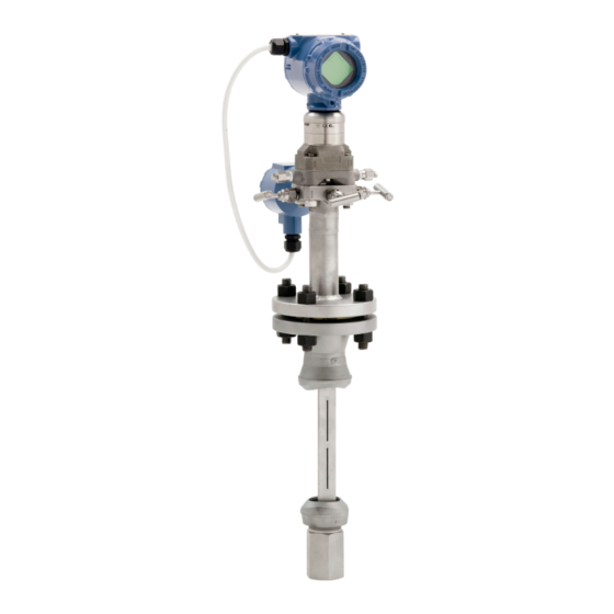
- Page 1 Quick Start Guide 00825-0100-4809, Rev DD March 2024 Rosemount 485 Annubar Flanged ™ ™ Assembly...
-
Page 2: Table Of Contents
Rosemount 485 Annubar Reference Manual for more instruction. This manual is also available electronically on Emerson.com/Rosemount. If the Rosemount Annubar was ordered assembled to a Rosemount Pressure Transmitter, see the following Quick Start Guides for information on configuration and hazardous... -
Page 3: Location And Orientation
March 2024 Quick Start Guide 1 Location and orientation Correct orientation and straight run requirements must be met for accurate and repeatable flow measurements. Refer to Table 1-1 minimum pipe diameter distances from upstream disturbances. Note • Consult the factory for instructions regarding use in square or rectangular ducts. - Page 4 Quick Start Guide March 2024 (continued) Table 1-1: Straight Run Requirements In plane Out of plane Upstream pipe diameters Downstream pipe Without With diameters straightening straightening vanes vanes Out of A’ C’ plane A plane A 3 4 4 N/A ...
- Page 5 March 2024 Quick Start Guide 1.1 Rosemount 485 Annubar Flange Assembly Note Use an appropriate pipe sealing compound rated for the service temperature on all threaded connections. Note Transmitter and housing are shown in Figure 1-1 for clarity purposes; transmitter and housing are only supplied if ordered. Figure 1-1: Rosemount 485 Annubar Flange Assembly Exploded View A.
- Page 6 Quick Start Guide March 2024 1.2 Misalignment Rosemount 485 Annubar installation allows for a maximum misalignment of 3°. Figure 1-2: Misalignment ±3° ±3° ±3° 1.3 Horizontal orientation Note The maximum temperature for a direct mounted transmitter is 500 °F (260 °C). Note For steam applications with DP readings between 0.75 and 2 inH in horizontal pipes, it is recommended to install the primary element/ flowmeter mounting above the pipe.
- Page 7 March 2024 Quick Start Guide Figure 1-3: Horizontal Orientation Liquid and steam Recommended zone 90° ±45° ±45° Recommended Recommended 45° 30° 45° zone 30° zone 30° Top mounting for steam Recommended Recommended 30° zone 30° zone 30° 45° 45°...
- Page 8 Quick Start Guide March 2024 Figure 1-4: Vertical Orientation Steam Liquid 360° 360° 360° 485 Annubar Flanged Assembly ™...
-
Page 9: Drill Sensor Holes
Drill to Hole Size P/N: 28-109001-922 Rev. AC WARNING When drilling the mounting hole(s), Emerson recommends the use of a magnetic drill or pipe clamping fixture to safely drill the hole. Use appropriate personal protective equipment and procedures when drilling and welding. - Page 10 Quick Start Guide March 2024 be drilled opposite the first hole so that the sensor can pass completely through the pipe. To drill the second hole, follow these steps: Note To determine if you have an opposite-side support model, measure the distance from the tip to the first slot or hole. If the distance is greater than 1 in.
-
Page 11: Assemble And Check Fit-Up
March 2024 Quick Start Guide 3 Assemble and check fit-up For accurate measurement, use the following steps to ensure that Ports A and B are equal distances from the inside walls of the pipe. Procedure 1. Assemble the Rosemount 485 to the mounting hardware with the gaskets and bolts. - Page 12 Quick Start Guide March 2024 Figure 3-1: Fit-up Check for Rosemount 485 Annubar with Opposite-Side Support Liquid or steam A. The same with ⅛″ (3 mm) B. Port A C. Port B D. Outer Diameter to Flange (ODF) E. Pipe outside diameter 485 Annubar Flanged Assembly ™...
-
Page 13: Weld Mounting Hardware
March 2024 Quick Start Guide 4 Weld mounting hardware Procedure 1. Center the flanged assembly over the mounting hole, gap 1/16 in. (1.6 mm), and measure the distance from the outer diameter of the pipe to the face of the flange. Compare this to Table 4-1 and adjust the gap as necessary. - Page 14 Quick Start Guide March 2024 (continued) Table 4-1: Flange Sizes and ODF per Sensor Size Sensor Flange size Size size 3.0 in. 600# 5.38 in. DN80 PN100 4.95 in. (136.6 mm) (125.6 mm) 4.0 in. 900# 8.19 in. (208.0 mm) 4.0 in. 1500# 8.56 in. (217.5 mm) 4.0 in.
-
Page 15: Insert The Rosemount Annubar
March 2024 Quick Start Guide 5 Insert the Rosemount Annubar Procedure 1. Align the flow arrow on the head with the direction of flow. Assemble the bar to the mounting flange using a gasket, bolts, and nuts. 2. Tighten the nuts in a cross pattern to allow even compression of the gasket. -
Page 16: Mount The Transmitter
Quick Start Guide March 2024 6 Mount the transmitter 6.1 Transmitter mounting, direct mount head with valves It is not necessary to retract the Rosemount Annubar when direct mounting a transmitter with valves. Procedure 1. Place PTFE O-rings into grooves on the Rosemount Annubar head. - Page 17 March 2024 Quick Start Guide 2. Outdoor installations for liquid, saturated gas, or steam may require insulation and heat tracing to prevent freezing. 3. An instrument manifold is recommended for all installations. Manifolds allow an operator to equalize the pressures prior to zeroing and isolates the process fluid from the transmitter.
- Page 18 Quick Start Guide March 2024 Table 6-1: Description of Impulse Valves and Components (continued) Name Description Purpose Manifold Allows high and low pressure side equalizer access to the vent valve, or for isolating the process fluid Manifold equalizer Manifold Allows high and low side pressure to equalizer equalize Manifold vent...
- Page 19 March 2024 Quick Start Guide Steam or liquid service Mount the transmitter below the process piping, adjust 10–15° above direct vertical down. Route the impulse piping down to the transmitter and fill the system with water through the two cross fittings. Figure 6-3: Steam or Liquid Service Vertical steam and liquid Horizontal steam and...
- Page 20 Quick Start Guide March 2024 Figure 6-4: Horizontal Top Mounting for Steam 485 Annubar Flanged Assembly ™...
-
Page 21: Product Certifications
7.1 Approved Manufacturing Locations Emerson Process Management – Shakopee, Minnesota, USA Rosemount DP Flow Design and Operations – Boulder, Colorado, USA Emerson Process Management GmbH & Co. OHG – Wessling, Germany Emerson Process Management Asia Pacific Private Limited – Singapore Emerson Beijing Instrument Co., Ltd –... - Page 22 Quick Start Guide March 2024 7.4 China RoHS 485 Annubar Flanged Assembly ™...
- Page 23 March 2024 Quick Start Guide Quick Start Guide...
- Page 24 2024 Emerson. All rights reserved. Emerson Terms and Conditions of Sale are available upon request. The Emerson logo is a trademark and service mark of Emerson Electric Co. Rosemount is a mark of one of the Emerson family of companies. All other marks are the property of their respective owners.
Need help?
Do you have a question about the Rosemount 485 Annubar Flanged and is the answer not in the manual?
Questions and answers