
Related Manuals for Emerson ROSEMOUNT 485 Annubar Pak-Lok


Summary of Contents for Emerson ROSEMOUNT 485 Annubar Pak-Lok
- Page 1 Quick Start Guide 00825-0300-4809, Rev EC May 2023 Rosemount 485 Annubar Pak-Lok ™ ™ Assembly...
-
Page 2: Table Of Contents
Flameproof, or Intrinsically Safe (I.S.) installations. Refer to Rosemount 485 Annubar Reference Manual for more instruction. This manual is also available electronically on Emerson.com/Rosemount. If the Rosemount Annubar was ordered assembled to a Rosemount Pressure Transmitter, see the following Quick Start Guides for information on configuration and hazardous... -
Page 3: Location And Orientation
May 2023 Quick Start Guide 1 Location and orientation Correct orientation and straight run requirements must be met for accurate and repeatable flow measurements. Refer to Table 1-1 minimum pipe diameter distances from upstream disturbances. Table 1-1: Straight Run Requirements In plane Out of plane Upstream pipe diameters Downstream pipe... - Page 4 “Out of plane A” means the bar is perpendicular to the plane of the elbow. • If proper lengths of straight run are not available, position the mounting such that 80% of the run is upstream and 20% is downstream. • Use straightening vanes to reduce the required straight run length. Emerson.com/Rosemount...
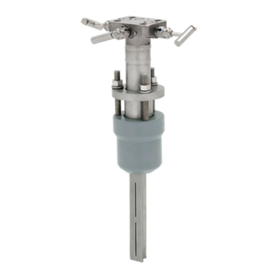
- Page 5 1.1 Exploded view drawings Figure 1-1: Rosemount 485 Annubar Pak-Lok Assembly Exploded View A. Transmitter B. Coplanar flange with drain vents C. 2 x O-rings D.
- Page 6 Quick Start Guide May 2023 Figure 1-2: Rosemount 485 Annubar Pak-Lok Assembly Detail Exploded View A. Nuts B. Follower C. 3 x Packing rings D. Studs E. Compression plate F. Retaining ring G. Rosemount 485 Annubar Sensor 1.2 Misalignment Rosemount 485 Annubar installation allows for a maximum misalignment of 3°.
- Page 7 May 2023 Quick Start Guide Figure 1-3: Misalignment ±3° ±3° ±3° Quick Start Guide...
- Page 8 Quick Start Guide May 2023 1.3 Flowmeter Orientation Figure 1-4: Flowmeter Orientation for Liquid Direct mount Horizontal liquid Vertical liquid 360° 45° 45° Recommended Recommended 30° zone 30° zone 30° Remote mount Horizontal liquid Vertical liquid Downward flow is not recommended. Emerson.com/Rosemount...
- Page 9 May 2023 Quick Start Guide Figure 1-5: Flowmeter Orientation for Gas Direct mount Horizontal gas Vertical gas 360° Recommended zone 90° 45° 45° Remote mount Horizontal gas Vertical gas Quick Start Guide...
- Page 10 Horizontal steam Vertical steam Downward flow is not recommended. Note For steam applications with DP readings between 0.75 and 2 inH O in horizontal pipes, consider installing the primary element/flowmeter mounting in the top mounting for steam configuration. Emerson.com/Rosemount...
- Page 11 May 2023 Quick Start Guide 1.4 Top mounting the flowmeter for steam Top mounting in steam is an alternative mounting method for steam installations that can be used if there are space restrictions or other concerns. This installation method is intended for applications that run with limited interruptions or shutdowns.
-
Page 12: Drill Sensor Holes
Drill to Hole Size P/N: 28-109001-922 Rev. AC WARNING When drilling the mounting hole(s), Emerson Process Management recommends the use of a magnetic drill or pipe clamping fixture to safely drill the hole. Use appropriate personal protective equipment and procedures when drilling and welding. - Page 13 May 2023 Quick Start Guide opposite-side support model, measure the distance from the tip to the first slot or hole. If the distance is greater than 1-in. (25.4 mm), it is the opposite-side support model.) To drill the second hole, follow these steps: a) Measure the pipe circumference with a pipe tape, soft wire, or string.
-
Page 14: Weld Mounting Hardware
4. To avoid serious burns, allow the mounting hardware to cool before continuing. LMH values are as follows: Sensor size 1 — 2.89-in. (73 mm) Sensor size 2 — 3.92-in. (100 mm) Sensor size 3 — 3.96-in. (101 mm) Emerson.com/Rosemount... -
Page 15: Insert The Rosemount Annubar
May 2023 Quick Start Guide 4 Insert the Rosemount Annubar Note Refer to Figure 1-1 for component descriptions. Procedure 1. Thread studs into the Pak-Lok body. 2. To ensure that the flowmeter contacts the opposite side pipe wall, mark the tip of the sensor with a marker. (Do not mark if ordered with option code P2 or PA.) 3. - Page 16 Install the second packing ring underneath the follower. Alternate packing ring splits by 120° to each other. d) Use the follower and the compression plate to compress the second packing ring against the first packing ring. Emerson.com/Rosemount...
- Page 17 May 2023 Quick Start Guide e) Install the third packing ring underneath the follower. f) Use the follower and the compression plate to compress the third packing ring against the second packing ring. 7. Tighten the nuts onto the studs: a) Place the included split-ring lock washer between each of the nuts and the compression plate.
- Page 18 Step 6 Step 7 to ensure the packing was installed correctly. If the gap is still not within tolerances, contact your Emerson Process Management representative for technical support. Table 4-2: Minimum and Maximum Gap Dimensions Sensor size Minimum gap in.
-
Page 19: Mount The Transmitter
May 2023 Quick Start Guide 5 Mount the transmitter 5.1 Transmitter mounting, direct mount head with valves It is not necessary to retract the Rosemount Annubar when direct mounting a transmitter with valves. Procedure 1. Place PTFE O-rings into grooves on the Rosemount Annubar head. - Page 20 DP sensor Drain/vent valve diaphragms Manifold Isolates high side or low side pressure from the process Manifold Manifold Allows high and low pressure side equalizer access to the vent valve, or for isolating the process fluid Manifold equalizer Emerson.com/Rosemount...
- Page 21 May 2023 Quick Start Guide Table 5-1: Description of Impulse Valves and Components (continued) Name Description Purpose Manifold Allows high and low side pressure to equalizer equalize Manifold vent Vents process fluid valve High pressure Low pressure Quick Start Guide...
-
Page 22: Product Certifications
6.1 Approved Manufacturing Locations Emerson Process Management – Shakopee, Minnesota USA Rosemount DP Flow Design and Operations – Boulder, Colorado USA Emerson Process Management GmbH & Co. OHG – Wessling, Germany Emerson Process Management Asia Pacific Private Limited – Singapore Emerson Beijing Instrument Co., Ltd –... -
Page 23: Declaration Of Conformity
May 2023 Quick Start Guide 7 Declaration of Conformity Figure 7-1: Rosemount Primary Element Declaration of Conformity Quick Start Guide... - Page 24 Quick Start Guide May 2023 Emerson.com/Rosemount...
- Page 25 May 2023 Quick Start Guide Quick Start Guide...
- Page 26 Quick Start Guide May 2023 Emerson.com/Rosemount...
-
Page 27: China Rohs
May 2023 Quick Start Guide 8 China RoHS Quick Start Guide... - Page 28 2023 Emerson. All rights reserved. Emerson Terms and Conditions of Sale are available upon request. The Emerson logo is a trademark and service mark of Emerson Electric Co. Rosemount is a mark of one of the Emerson family of companies. All other marks are the property of their respective owners.
Need help?
Do you have a question about the ROSEMOUNT 485 Annubar Pak-Lok and is the answer not in the manual?
Questions and answers