Table of Contents
Advertisement
Quick Links
Advertisement
Table of Contents

Related Manuals for Stuv 6 86X60


Summary of Contents for Stuv 6 86X60
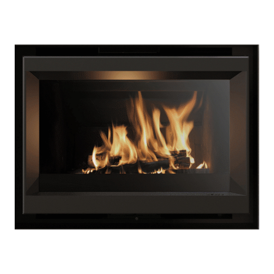
- Page 1 STUV 6 (86 X 60 MODEL) SPECIFICATIONS & MANUFACTURER INSTALLATION GUIDE...
- Page 2 Congratulations on your purchase of the STUV 6. This appliance should be installed and checked by a qualified professional. Ensure you have read the operation guidelines thoroughly prior to first use. CAUTION: Using components or parts other than those provided by the manufacturer or modifying the specification of components may result in inferior or unsafe operation.
-
Page 3: Dimensions & Technical Data
DIMENSIONS & TECHNICAL DATA STUV 6 - DIMENSIONS OF THE DEVICE WITHOUT THE DECORATIVE FRAME AND WITHOUT OPTIONAL EXTRAS 813 mm WEIGHT AND DIMENSIONS: Firebox external dimensions W822 x H588 x D413mm Firebox weight 115Kg Flue system Solid 6” or Flexi 6”... - Page 4 CONNECTION TO THE COMBUSTION SMOKE OUTLET PIPE Smoke outlet connection piece (vertical or 45º angle) FINISH Decorative frames OPTIONS Stand Nozzle Ø100mm for external air inlet from the bottom Rear external air connection kit Ø100mm STUV 6 | SPECIFICATIONS & MANUFACTURER INSTALLATION GUIDE PAGE 4...
- Page 5 Thin flush frame Stuv 6 – 86 x 60 *Expansion joint that must be respected around the decorative frame THIN EXTENDED FRAME (mm) Thin extended frame Stuv 6 – 86 x 60 STUV 6 | SPECIFICATIONS & MANUFACTURER INSTALLATION GUIDE PAGE 5...
- Page 6 Applied frame 4 sides Stuv 6 – 86 x 60 (-0/+20) (-0/+20) (-0/+20) FITTED FRAME 3 SIDES (mm) Applied frame 3 sides Stuv 6 – 86 x 60 (-0/+20) (-0/+20) (-0/+20) STUV 6 | SPECIFICATIONS & MANUFACTURER INSTALLATION GUIDE PAGE 6...
- Page 7 6” FLUE AND 100 AIR INTAKE CONNECTIONS Dimensions of the smoke outlet at 45° Dimensions of the smoke outlet upwards STUV 6 | SPECIFICATIONS & MANUFACTURER INSTALLATION GUIDE PAGE 7...
- Page 8 6” FLUE AND 100 AIR INTAKE CONNECTIONS Dimensions of the connection to the external air inlet at the rear Dimensions of the connection to the external air inlet at the bottom STUV 6 | SPECIFICATIONS & MANUFACTURER INSTALLATION GUIDE PAGE 8...
- Page 9 ADJUSTABLE FIREBOX STAND Dimensions of the stand 50 to 600 STUV 6 | SPECIFICATIONS & MANUFACTURER INSTALLATION GUIDE PAGE 9...
-
Page 10: Framing & Clearances
2.2 FRAMING CLEARANCES MASONRY INSTALLATION Stuv 6 is a zero clearance box to masonry. Allowing a small expansion gap is recommended to prevent possible damages to the firebox or surrounding materials. IMPORTANT: The fireplace is not load bearing CLEARANCES TO COMBUSTIBLE MATERIAL... -
Page 11: Floor Protector
Floor protector must be minimum 9mm thick cement sheet (excluding non combustible floor finish) 735mm Combustible floor 300mm 9mm cement sheet 400mm or higher Finished non combustible floor 1125mm 300mm STUV 6 | SPECIFICATIONS & MANUFACTURER INSTALLATION GUIDE PAGE 11... - Page 12 SETTING UP THE CONNECTIONS The STUV 6 is specifically designed so that it is easy to connect to outside air intake (optional) and smoke outlet (flue). The connections are carried out from the inside of the unit once fitted. So before fitting the unit, prepare the connections as per below: OUTSIDE AIR INTAKE - REAR OR BACK (OPTIONAL) Install the air inlet duct and attach the nozzle with a metal duct clamp.
- Page 13 GETTING THE UNIT READY FOR INSTALL Dismantling the unit allows an easier handling process and give access to the different connections STEP 1: DISMANTLE THE DOOR STEP 2: REMOVE THE SMOKE DEFLECTORS STUV 6 | SPECIFICATIONS & MANUFACTURER INSTALLATION GUIDE PAGE 13...
- Page 14 GETTING THE UNIT READY FOR INSTALL STEP 3: SEPARATING SUPPORT CASING & COMBUSTION CHAMBER STUV 6 | SPECIFICATIONS & MANUFACTURER INSTALLATION GUIDE PAGE 14...
- Page 15 THREE OPTIONS FOR COMBUSTION AIR SUPPLY OPTION #1: BOTTOM CONNECTION OPTION #2: REAR CONNECTION STUV 6 | SPECIFICATIONS & MANUFACTURER INSTALLATION GUIDE PAGE 15...
- Page 16 If you choose to get the air for combustion through the frame make sure you follow these simple steps: 1. Remove the head 2. Remove the 2 3. Remove the 2 plates and from the Damper. side screws. the spring. 4. Put the Damper Head back on. STUV 6 | SPECIFICATIONS & MANUFACTURER INSTALLATION GUIDE PAGE 16...
- Page 17 POSITIONING THE OUTER CASING OPTION #1: OUTER CASING INSTALL IN A RECESS OPTION #2: OUTER CASING INSTALLED ON ITS STAND 600-X mm = 50-200mm min. 50mm STUV 6 | SPECIFICATIONS & MANUFACTURER INSTALLATION GUIDE PAGE 17...
- Page 18 REASSEMBLING THE COMBUSTION CHAMBER IN THE OUTER CASING STUV 6 | SPECIFICATIONS & MANUFACTURER INSTALLATION GUIDE PAGE 18...
-
Page 19: Connecting The Flue
Once the smoke outlet is in position, use pliers to break the handle off [figures 4 & 5]. N.B.: The smoke outlet can be turned to make it easier to connect to the duct [figure 2]. STUV 6 | SPECIFICATIONS & MANUFACTURER INSTALLATION GUIDE PAGE 19... -
Page 20: Fitting The Decorative Frame
FITTING THE DECORATIVE FRAME OPTION #1: FITTING THE THIN FRAME OPTION #2: FITTING THE ADJUSTABLE 3 OR 4 SIDED FRAME STUV 6 | SPECIFICATIONS & MANUFACTURER INSTALLATION GUIDE PAGE 20... - Page 21 If you have a “lazy’” chimney, you can lower the housing to the second or third notches (figure 2). Use the markings on the side to get the right position for the deflector housing (figure 3). STUV 6 | SPECIFICATIONS & MANUFACTURER INSTALLATION GUIDE PAGE 21...
-
Page 22: Flue Installation
The top of the flue must be 400mm higher than the highest point of the roof. Alternatively, there must be a minimum distance of 3 meters from any higher section of roof. > 3 m > 40 cm – – > 40 cm – > 40 cm – STUV 6 | SPECIFICATIONS & MANUFACTURER INSTALLATION GUIDE PAGE 22... -
Page 23: Operation
WARNING: • The Maximum load capacity of the STUV 6 is 4 kg of Hardwood/hour. • Overloading the unit may result in damaging the heater and voiding the warranty. • Misuse may lead to unhealthy and environmentally harmful emissions. -
Page 24: Test Report
AS/NZS 4012, AS/NZS 4013 (2014). CONCLUSION: The Stuv 6 Insert solid fuel burning appliance complies with the requirement of a combined efficiency of not less than 60% and a particulate emissions factor of not greater than 1.5g/kg of hardwood that complies to AS/NZS4014.
Need help?
Do you have a question about the 6 86X60 and is the answer not in the manual?
Questions and answers