
Related Manuals for HMS Networks Intesis INMBSDAI001I000


Summary of Contents for HMS Networks Intesis INMBSDAI001I000
- Page 1 ENGLISH INMBSDAI001I000 Modbus RTU Gateway COMPATIBLE WITH DOMESTIC AIR CONDITIONING SYSTEMS COMMERCIALIZED BY DAIKIN USER MANUAL Version 1.0.0 Publication date 2024-01-23...
- Page 2 The information in this document shall therefore not be construed as a commitment on the part of HMS Networks and is subject to change without notice. HMS Networks makes no commitment to update or keep current the information in this document.
-
Page 3: Table Of Contents
INMBSDAI001I000 Modbus RTU Gateway Table of Contents 1. Description and Order Codes ..................... 1 2. General Information ........................ 2 2.1. Intended Use of the User Manual ..................2 2.2. General Safety Information ....................2 2.3. Admonition Messages and Symbols ..................2 3. -
Page 4: Description And Order Codes
Description and Order Codes INMBSDAI001I000 Modbus RTU Gateway 1. Description and Order Codes Modbus RTU (EIA-485) Gateway for Daikin Air Conditioners. Compatible with domestic air conditioning systems commercialized by Daikin. Use the compatibility tool to get a complete list of compatible AC units: https://compatibility.intesis.com/# ORDER CODE LEGACY ORDER CODE... -
Page 5: General Information
INMBSDAI001I000 Modbus RTU Gateway General Information 2. General Information 2.1. Intended Use of the User Manual This manual contains the main features of this Intesis gateway and the instructions for its appropriate installation, configuration, and operation. The contents of this manual should be brought to the attention of any person who installs, configures, or operates this gateway or any associated equipment. - Page 6 Admonition Messages and Symbols INMBSDAI001I000 Modbus RTU Gateway NOTE Additional information which may facilitate installation and/or operation. Helpful advice and suggestions. NOTICE Remarkable Information. USER MANUAL Version 1.0.0 Page 3 of 23...
-
Page 7: Overview
The Intesis INMBSDAI001I000 gateway provides full integration of Daikin air conditioners into Modbus RTU (EIA-485) networks. Figure 1. Integration of Daikin AC units into a Modbus RTU installation using the Intesis INMBSDAI001I000 gateway. IMPORTANT This document assumes that the user is familiar with these technologies. -
Page 8: Quickstart Guide
Quickstart Guide INMBSDAI001I000 Modbus RTU Gateway 3.3. Quickstart Guide IMPORTANT Disconnect all systems from the power source before connecting them to the gateway. NOTE DIN rail mounting inside a grounded cabinet or metal enclosure is recommended. Mount the Intesis gateway in the desired installation site. Connect the gateway to the Modbus RTU network via its EIA-485 port. -
Page 9: Hardware
INMBSDAI001I000 Modbus RTU Gateway Hardware 4. Hardware 4.1. Mounting IMPORTANT Before mounting, please ensure that the chosen installation place preserves the gateway from direct solar radiation, water, high relative humidity, or dust. NOTE Mount the gateway on a wall or over a DIN rail. DIN rail mounting inside a grounded metallic cabinet is recommended. -
Page 10: Connections
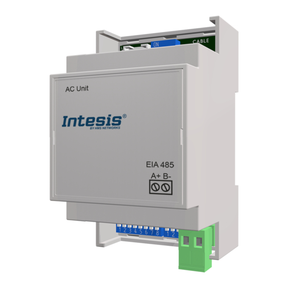
Connections INMBSDAI001I000 Modbus RTU Gateway 4.2. Connections NOTE • Use the supplied specific cable for connection to the AC unit. CAUTION Disconnect all systems from the power source before manipulating and connecting them to the gateway. 4.2.1. Gateway Connectors Figure 2. General view of all gateway connectors NOTE Mount the gateway in the desired installation site before wiring. -
Page 11: Connection Procedure For Modbus
INMBSDAI001I000 Modbus RTU Gateway Connections Use the supplied cable. Plug the mating connector into the S21 socket, then click-fit the other end's connector into the INMBSDAI001I000 socket marked as AC unit. Fit the unit front cover before powering on. IMPORTANT Do not modify the length of the supplied cable, as it may affect the device operation. -
Page 12: Gateway Layout
Gateway Layout INMBSDAI001I000 Modbus RTU Gateway 4.3. Gateway Layout Find in this image below the disposition of various hardware elements in the gateway. Figure 3. Gateway layout The following sections explain LEDs and DIP switches in more detail. 4.4. Device LED indications The device features a LED for indication of operational status. -
Page 13: Dip Switch Configuration
INMBSDAI001I000 Modbus RTU Gateway DIP Switch Configuration 4.5. DIP Switch Configuration See figure: Gateway layout (page 9) All the configuration settings on the INMBSDAI001I000 gateway can be written and read from the Modbus interface. Some of these settings can also be set up from the gateway's onboard DIP switch blocks. The following tables apply to the interface configuration through DIP switches: NOTICE DIP-Switch SW1 is not used by the current version of the INMBSDAI001I000 gateway. - Page 14 DIP Switch Configuration INMBSDAI001I000 Modbus RTU Gateway Table 5. DIP switch SW3: Modbus server address setting Address Binary 0 0 0 0 0 0 X X ↓ ↓ ↓ ↓ ↓ ↓ X X 1 0 0 0 0 0 X X ↑...
-
Page 15: Technical Specifications
INMBSDAI001I000 Modbus RTU Gateway Technical Specifications 4.6. Technical Specifications Housing Plastic, PC type (UL 94 V-0) Net dimensions (DxWxH): Millimeters: 93 x 53 x 58 mm Inches: 3.7 x 2.1 x 2.3" Color: Light grey. RAL 7035 Weight 85 g Mounting Wall DIN rail EN60715 TH35... -
Page 16: Dimensions
Dimensions INMBSDAI001I000 Modbus RTU Gateway 4.7. Dimensions • Net dimensions (DxWxH) Millimeters: 93 x 53 x 58 mm Inches: 3.6 x 2.1 x 2.3" • Clear space for installation (DxWxH) Millimeters: 100 x 60 x 70 mm Inches: 3.9 x 2.4 x 2.7" USER MANUAL Version 1.0.0 Page 13 of 23... -
Page 17: Modbus Interface Specification
INMBSDAI001I000 Modbus RTU Gateway Modbus Interface Specification 5. Modbus Interface Specification 5.1. Modbus Physical Layer The INMBSDAI001I000 gateway implements a Modbus RTU (server) interface to be connected to an EIA-485 bus. It features 8-N-2 communication (eight data bits, no parity, and two stop bits) with several baud rates available (2400 bps, 4800 bps, 9600 bps -default-, 19200 bps, 38400 bps, 57600 bps, 76800 bps, and 115200 bps). - Page 18 Modbus Registers INMBSDAI001I000 Modbus RTU Gateway Register Address Register Address Description (protocol address) (PLC address) 1,2,3 AC unit Temperature Setpoint -32768 (initialization value) COOL 18 .. 32°C 64 .. 90°F HEAT R, W 16 .. 30°C 61 .. 86°F AUTO 18 ..
-
Page 19: Configuration Registers
INMBSDAI001I000 Modbus RTU Gateway Modbus Registers Register Address Register Address Description (protocol address) (PLC address) AC unit Left/Right Vane Position 0: Auto (default value) R, W 10: Swing AC Humidification Value 0: Off 1: Low Humidification R, W 2: Medium Humidification 3: High Humidification 4: Continuous 4,7,8... -
Page 20: Considerations On Temperature Registers
Modbus Registers INMBSDAI001I000 Modbus RTU Gateway 5.2.3. Considerations on Temperature Registers • AC unit temperature setpoint (R/W) (protocol address register 4 / PLC address register 5) This is the adjustable temperature setpoint value required by the user. This value can be read and written. A remote controller connected to the Daikin indoor unit will report the same temperature setpoint value as this register. -
Page 21: Implemented Modbus Functions
INMBSDAI001I000 Modbus RTU Gateway Implemented Modbus Functions When the gateway detects a change of any of the values of {S , or T }, it will send the new setpoint ) to the indoor unit. After a device boot, the value for the external temperature reference (register 22/23) is -32768 (0x8000). This value means that no external temperature reference has yet been provided to the object, so the system is not applying the virtual temperature function. -
Page 22: Termination Resistors And Fail-Safe Biasing Mechanism
Termination resistors and Fail-safe Biasing Mechanism INMBSDAI001I000 Modbus RTU Gateway 5.4. Termination resistors and Fail-safe Biasing Mechanism IMPORTANT The EIA-485 bus requires a 120 Ω termination resistor at each end to avoid signal reflections. In order to prevent fail status detections by bus receivers when all the transmitters' outputs are in a high- impedance state, a fail-safe biasing mechanism is required. -
Page 23: Error Codes
INMBSDAI001I000 Modbus RTU Gateway Error Codes 6. Error Codes Find below a list of error codes for Daikin air conditioning systems Table 8. Daikin Error Codes Error Code Error in Remote Controller Error Category Error description INMBSDAI001I000 No active error External protection devices activated Indoor unit PCB assembly failure Interlock error for fan... - Page 24 Error Codes INMBSDAI001I000 Modbus RTU Gateway Error Code Error in Remote Controller Error Category Error description Malfunctions in a drain water Ice thermal storage unit error Malfunctions in a sensor system Air temperature thermistor error Sensor system of power supply error High Pressure switch is faulty Low pressure switch is faulty Compressor motor overload sensor is abnormal...
- Page 25 INMBSDAI001I000 Modbus RTU Gateway Error Codes Error Code Error in Remote Controller Error Category Error description Stall prevention error (start-up error) Compressor locked, etc. Power transistor error Communication error between inverter and outdoor control unit Shortage of refrigerant (thermal storage unit) Power voltage imbalance, open phase Sensor error of temperature rise in a switch box Radiation fin temperature sensor error...
- Page 26 Error Codes INMBSDAI001I000 Modbus RTU Gateway Error Code Error in Remote Controller Error Category Error description Inverter system error (supply air side) Inverter system error (return air side) Humidifying valve error Chilled water valve error Hot water valve error Heat exchanger of chilled water error Heat exchanger of hot water error The humidity sensor of return air sensor Outdoor air humidity sensor error...
Need help?
Do you have a question about the Intesis INMBSDAI001I000 and is the answer not in the manual?
Questions and answers