WESTERSTRAND Lumex 5 User Manual
Hide thumbs
Also See for Lumex 5:
- Instructions manual (17 pages) ,
- Instructions manual (15 pages) ,
- Instructions manual (16 pages)

Subscribe to Our Youtube Channel
Related Manuals for WESTERSTRAND Lumex 5


Summary of Contents for WESTERSTRAND Lumex 5
- Page 1 User Manual 1862en09 Westerstrand Time System 2024-02-05 User Manual Digital clock Lumex 5, Lumex 7, Lumex 12 Lumex 5S, Lumex 7S, Lumex 12S Westerstrand Urfabrik AB Box 133, SE-545 23 Töreboda www.westerstrand.se Tel.: +46 506 48000 info@westerstrand.se...
-
Page 2: Table Of Contents
1862en09 2024-02-05 2 (16) Index General ..............................3 Safety ............................... 3 Installation ............................... 4 Connection .............................. 6 Synchronisation ............................9 Connection temperature sensor (option)..................... 10 Programming ............................11 Technical Specification .......................... 16... -
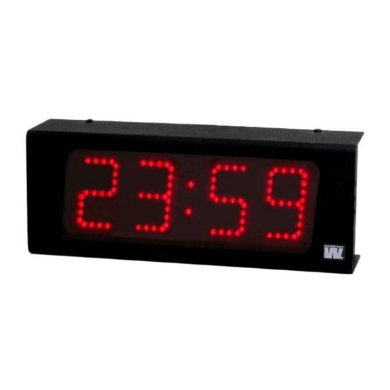
Page 3: General
1862en09 2024-02-05 3 (16) General Digital clock for indoor application has 4 digits and colon displaying time. The digits consist of 7 segments. 23:59 Exempel Digital clock for indoor application with second has 6 digits and colon displaying time. The digits for the second consist of 7 segments. -
Page 4: Installation
1862en09 2024-02-05 4 (16) Installation Installation/Montering Vägg-modell Installation wall mounted • Unscrew 4 screws, 2 above and 2 under, remove the back plate from the casing and mount it on the wall. • If operated by synchronisation, check the strapping according to the drawing page 7. Connect the cables according the schema page 6. - Page 5 1862en09 2024-02-05 5 (16) Installation wall mounted • Unscrew 2 screws under the service front. (The front when you have R,F,P buttons to the right.) Remove the front. • Mount the digital clock. • If operated by synchronisation, check the strapping according to the drawing page 7. Connect the cables according the schema page 6.
-
Page 6: Connection
1862en09 2024-02-05 6 (16) Connection The connections are made on the inside of the back plate (see below.) Disconnect power before hard installation. The cable must be double-insulated and stripped to a maximum of 3 cm. It must also be secured with the cable relief. Connection Synchronisation wire TC/MIN-imp 3,4 DCF 2-line... - Page 7 1862en09 2024-02-05 7 (16) Strapping/DIP switch setting for TC / MIN-impulse (default) Strapping/DIP switch setting for DCF-radio (2 –wire) computer board...
- Page 8 1862en09 2024-02-05 8 (16) Strapping/DIP switch setting for DCF-radio (3 –wire) computer board The DIP-switch on the computer board should be set as follows: Dip 1: OFF Display format is HH:MM. Display format is HH:MM:SS. Dip 2: OFF always OFF Dip 3: OFF TC/Min impulse-synchronisation.
-
Page 9: Synchronisation
1862en09 2024-02-05 9 (16) Synchronisation Stand-alone If the clock does not have an external synchronisation, it operates Stand-alone. Minute impulse Make the strapping according to the drawing for strapping page 7. Connect the minute impulse wire according to the schema page 6. The clock can be set in synchronisation or slave mode. -
Page 10: Connection Temperature Sensor (Option)
1862en09 2024-02-05 10 (16) Connection temperature sensor (option). Temperature sensor connection: 1. Brown 2. Black 5. Screen Sync. input... -
Page 11: Programming
1862en09 2024-02-05 11 (16) Programming The programming is made by push buttons (see below). R (Return) Enter the base mode (display time) F (Function) Next function / Accept displayed value P (Program) Enter the displayed function / Increase displayed value. Programming time ti ne Push [F] until display shows:... - Page 12 1862en09 2024-02-05 12 (16) Push [P] until desired month (1-12). Accept with [F]. Display show: d d 1 Push [P] until desired date (1-31). Accept with [F]. hh 12 Display show: hour Push [P] until desired hour (0-23). Accept with [F]. nn 07 Display show: minute...
- Page 13 1862en09 2024-02-05 13 (16) Setting light intensity The light intensity for the digits can be adjusted in 8 levels. An automatic dimmer function regulates the light intensity. di sp Push [F] until display shows: Push [P] di 1 Display show: Light intensity 1 (weakest) - 8 (strongest) Push [P] for desired light intensity.
- Page 14 1862en09 2024-02-05 14 (16) Setting alternating time, Loop time LooP Push [F] until display show: Push [P]. L1 4 Display show: Alternating time for display time is 4 seconds. Push [P] for desired alternating time (0-25). Accept with [F]. Display show: Alternating time for display temp.
- Page 15 1862en09 2024-02-05 15 (16) Setting DLS-function. With this function the DLS can be activated. Push [F] until display show: Push [P]. Display show: Push [P] for DLS or not. Push [R] for entering base mode or push [F] for next function. Setting12/24 h format With this function the format 12/24 hours display can be set.
-
Page 16: Technical Specification
1862en09 2024-02-05 16 (16) Technical Specification General Art.no.: Lumex 5, LUMEX 5S, LUMEX 7, LUMEX 7S, LUMEX 12, LUMEX 12S Mounting/Installation: Single-, double sided. Wall or ceiling mounted. Digits HH:MM: 120/70/50mm, red, green, yellow, white SMD LED:s Digits SS: 70/50/37 mm, red, green, yellow, white SMD LED:s...
Need help?
Do you have a question about the Lumex 5 and is the answer not in the manual?
Questions and answers