Table of Contents
Advertisement
Quick Links
Advertisement
Table of Contents

Related Manuals for Cosmo COS-GRC305KTD


Summary of Contents for Cosmo COS-GRC305KTD
- Page 1 GAS RANGE COS-GRC305KTD 30" SLIDE-IN RANGE INSTALLATION INSTRUCTIONS IMPORTANT: READ AND SAVE THESE INSTRUCTIONS. FOR RESIDENTIAL USE ONLY. INSTALLER: PLEASE LEAVE THESE INSTRUCTIONS WITH THIS UNIT FOR THE OWNER. OWNER: PLEASE RETAIN THESE INSTRUCTIONS FOR FUTURE REFERENCE. Rev.23.11...
- Page 2 COSMO Appliances are designed according to the strictest safety and performance standard for the North American market. We follow the most advanced manufacturing philosophy.
-
Page 3: Table Of Contents
TABLE OF CONTENTS RANGE SAFETY....................4 Anti-tip Device ......................6 INSTALLATION REQUIREMENTS ................ 7 Tools and Parts ......................7 Location Requirements .................... 9 Product Specifications .................... 10 Product Dimensions ....................11 Clearances ......................... 12 Venting Requirements ..................... 14 Electrical Requirements ................... 15 Gas Supply Requirements .................. -
Page 4: Range Safety
RANGE SAFETY READ ALL INSTRUCTIONS BEFORE USING THE APPLIANCE Your safety and the safety of others are very important. We have provided many important safety messages in this manual and on your appliance. Always read and obey all safety messages. This is the safety alert symbol. - Page 5 WARNING FIRE AND EXPLOSION HAZARD If the information in this manual is not followed exactly, a fire or explosion may result causing property damage, personal injury or death. - Do not store or use gasoline or other flammable vapors and liquids in the vicinity of this or any other appliance.
-
Page 6: Anti-Tip Device
WARNING TIP OVER HAZARD • A child or adult can tip the range and be killed. • Install anti-tip bracket to floor or wall per installation instructions. • Slide range back so rear range foot is engaged in the slot of the anti-tip bracket. -
Page 7: Installation Requirements
INSTALLATION REQUIREMENTS TOOLS AND PARTS Gather the required tools and parts before starting installation. Read and follow the instructions provided with any tools listed here. Tools Needed • Tape measure • Marker or pencil • Flat-blade screwdriver • Pipe-joint compound resistant to Propane gas •... - Page 8 Parts Supplied Surface burner grates (3) Surface burners and caps (5) Oven racks (2) Anti-tip bracket with screws Gas pressure regulator Rear trim with screws (die cast) Optional Parts To purchase these or any other accessories or replacement parts, please visit www.cosmoappliances.com or reference the contact information at the end of this manual.
-
Page 9: Location Requirements
LOCATION REQUIREMENTS IMPORTANT: Observe all governing codes and ordinances. Do not obstruct flow of combustion and ventilation air. • It is the installer's responsibility to comply with installation clearances specified on the model/serial/rating plate. The model/serial/rating plate is located inside the storage drawer on either the left or right side panel. Model/Serial/Rating Plate •... -
Page 10: Product Specifications
Four-wire power supply cord or cable must be used in a mobile home installation. The appliance wiring will need to be revised. See "Electrical Connection" section. PRODUCT SPECIFICATIONS Model COS-GRC305KTD Description 30" Gas Range Oven Capacity 6.1 cu. ft. Electrical Requirements... -
Page 11: Product Dimensions
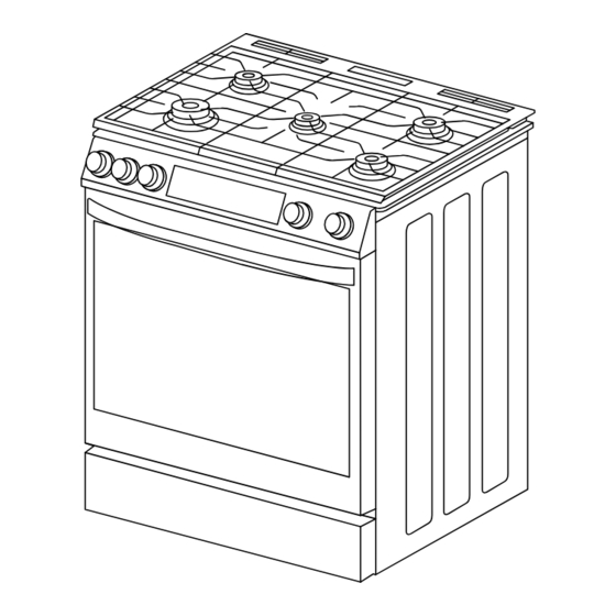
PRODUCT DIMENSIONS Your model may appear different from the model depicted. Dimensions given are maximum dimensions across all models. COS-GRC305KTD 31 ¹⁄ " (78.9 cm) With cooktop flanges 35 ¹⁄ " (90.2 cm) 38 ¹⁄ " Min. height (96.6 cm) -
Page 12: Clearances
CLEARANCES IMPORTANT: Some cabinet and building materials are not designed to withstand the heat produced by the oven for baking and self-cleaning. Check with your builder or cabinet supplier to make sure that the materials used will not discolor, delaminate or sustain other damage. GIVEN DIMENSIONS ARE MINIMUM CLEARANCES. - Page 13 Power Supply Location IMPORTANT: An electrical outlet in the floor, may be either recessed or surface mounted, but an electrical outlet in the wall must be recessed to make the connection. SLIDE-IN 4" 25" 23 ¹¹/ " 4" Gas supply area Electric supply 7"...
-
Page 14: Venting Requirements
VENTING REQUIREMENTS IMPORTANT: This range must be exhausted outdoors unless you are using ductless venting. Observe all governing codes and ordinances. Do not obstruct flow of combustion and ventilation air. • Do not terminate the vent system in an attic or other enclosed area. •... -
Page 15: Electrical Requirements
ELECTRICAL REQUIREMENTS WARNING ELECTRICAL SHOCK HAZARD • Electrically ground range. • Failure to do so can result in death, fire or electrical shock. ELECTRICAL GROUNDING INSTRUCTIONS • The power cord of this appliance is equipped with a three-prong (grounding) plug which plugs into a standard three-prong grounding wall receptacle to minimize the possibility of electric shock hazard from this appliance. - Page 16 WARNING: Improper connection of the equipment-grounding conductor can result in a risk of electric shock. Check with a qualified electrician or service technician if you are in doubt as to whether the appliance is properly grounded. Do not modify the power supply cord plug. If it will not fit the outlet, have a proper outlet installed by a qualified electrician.
-
Page 17: Gas Supply Requirements
GAS SUPPLY REQUIREMENTS WARNING FIRE AND EXPLOSION HAZARD • Use a new CSA International approved gas supply line. • Install a shut-off valve. • Securely tighten all gas connections. • If connected to LP, have a qualified person make sure gas pressure does not exceed the maximum pressure listed in this section. - Page 18 TYPE OF GAS This range is design-certified by CSA International for use with natural gas or, after proper conversion, for use with Liquid Propane (LP) gas. Natural Gas This range is factory-set for use with Natural gas. The model/serial/rating plate located inside the storage drawer on either the left or right side panel has information on the types of gas that can be used.
- Page 19 Rigid Pipe Connection Since the range must be pulled away from the installation space to provide access to the gas regulator connections, and because hard piping restricts movement of the range, the range can only be installed using a CSA International-certified flexible metal appliance connector.
- Page 20 HIGH ALTITUDE INSTALLATION WARNING CARBON MONOXIDE HAZARD • Reduced air pressure and oxygen availability at high altitudes may affect proper burner combustion. • Failure to properly convert the range for high altitude installations can result in increased risk carbon monoxide. •...
-
Page 21: Installation Instructions
INSTALLATION INSTRUCTIONS IMPORTANT: This appliance shall be installed only by authorized persons and in accordance with the manufacturer's installation instructions, local gas fitting regulations, municipal building codes, electrical wiring regulations, local water supply regulations. REMOVE OLD APPLIANCE WARNING FIRE AND EXPLOSION HAZARD - If the information in this manual is not followed exactly, a fire or explosion may result causing property damage, personal injury or death. -
Page 22: Unpack Range
CAUTION LACERATION, FOREIGN OBJECT, CRUSH HAZARD • When installing, moving, or servicing any appliance, wear proper protective equipment, including cut resistant gloves, steel-toed shoes, and safety glasses. • Shut off the main gas supply valve to the residence before disconnecting the old range and leave it off until the new hookup has been completed. -
Page 23: Install Anti-Tip Device
NOTE: • To further reduce the weight of the range while being moved, adjusted, and installed, detach the oven door and remove the bottom drawer from the range. See "Removing/Assembling Oven Door" and "Removing/Assembling Drawer" sections. INSTALL ANTI-TIP DEVICE WARNING TIP OVER HAZARD •... - Page 24 1. Using the template provided with anti-tip kit, locate the preferred location for installation of the anti-tip bracket and mark the location of the screw holes. Bracket may be installed at either the back-left or back- right corner of the installation space. Installation with Installation with rear left leg...
-
Page 25: Install Rear Trim
INSTALL REAR TRIM (OPTIONAL) If there is no counter surface around the back edge of the installation space, or if the countertop cutout is greater than 25" deep, this may prevent the range from being installed flush to the back wall. A rear trim can be installed to cover a gap up to 1 inch in width. -
Page 26: Gas Connection
GAS CONNECTION WARNING FIRE AND EXPLOSION HAZARD • Use a new CSA International approved gas supply line. • Install a shut-off valve. • Securely tighten all gas connections. • If connected to LP, have a qualified person make sure gas pressure does not exceed the maximum pressure listed in the "Gas Supply Requirement"... - Page 27 TYPICAL FLEXIBLE CONNECTION Pressure regulator 1/2" Adapter Gas shut-off valve Flexible connector 1/2" Adapter 1/2" or 1/4" (6 ft. max.) Gas pipe 1. Turn manual shut-off valve to the closed position. 2. Unplug range or disconnect power. 3. Locate and remove the regulator access cover on the back of the range. IMPORTANT: Do not remove the gas pressure regulator.
- Page 28 4. Apply pipe-joint compound made for use with LP gas to the smaller thread ends of the flexible connector adapters. 5. Attach male 1/2" flare union adapter to the 1/2" NPT internal thread at the regulator inlet with a wrench using no more than 15 ft-lbs of torque. Use a backup wrench on the regulator fitting to avoid damage.
- Page 29 CONVERT TO LP GAS (OPTIONAL) This range is shipped from the factory set up to use natural gas. It can be converted to operate on LP/propane gas by a qualified service technician. The LP conversion kit is sold separately. The conversion to LP requires all surface and oven burner gas orifices to be changed.
-
Page 30: Complete Installation
2. Open the manual shut-off valve in the gas supply line. The valve is open when the handle is parallel to the gas pipe. 3. Test all connections by brushing on an approved noncorrosive leak- detection solution. If bubbles appear, a leak is indicated. Correct any leak found. -
Page 31: Placement And Leveling Range
PLACEMENT AND LEVELING RANGE WARNING EXCESSIVE WEIGHT HAZARD • Use two or more people to move and install range. Failure to do so can result in back or other injury. CAUTION LACERATION, FOREIGN OBJECT, CRUSH HAZARD • When installing, moving, or servicing any appliance, wear proper protective equipment, including cut resistant gloves, steel-toed shoes, and safety glasses. - Page 32 1. Use tape measure to measure from the floor to the top of the countertop at all four corners of the installation space. 2. While range is still positioned outside the installation space, use a plier or wrench to adjust the leveling leg at each corner so that the distance from the floor to the underside of the cooktop edge matches the dimensions measured in the installation space.
-
Page 33: Verify Anti-Tip Bracket Engagement
4. Check to ensure the flexible metal gas connector and electrical cord are not kinked. 5. Place the level diagonally on the oven bottom or oven rack, and check each diagonal direction for level. Adjust the leveling legs with a plier or wrench as necessary. - Page 34 1. Place the outside of your foot against the bottom of the front panel to keep the range from moving, and then grasp the back of the range, as shown. 2. Carefully and slowly attempt to tilt the range forward. •...
-
Page 35: Removing/Assembling Oven Door
REMOVING/ASSEMBLING OVEN DOOR For normal range use, it is not suggested to remove the oven door. However, if removal is necessary, make sure the oven is off and cool. NOTE: • The oven door is heavy. • If door is removed, confirm that door operates correctly and seals properly when reinstalled. - Page 36 Assembling Door 1. Firmly grasp both sides of the door. 2. With the door at the same angle as the removal position, which is approximately five degrees or 2-3 inches from being fully closed, seat the indentation of the hinge arms into the bottom edge of the hinge slots.
-
Page 37: Removing/Assembling Drawer
REMOVING/ASSEMBLING DRAWER Removing Drawer 1. Fully open the drawer. 2. Locate the glide lever on each side of the drawer. Operate the release levers and pull the drawer away from the range. Assembling Drawer 1. Align the glide on each side of the drawer with the glide slots on the range. -
Page 38: Assembling The Surface Burners And Grates
ASSEMBLING THE SURFACE BURNERS AND GRATES IMPORTANT: Do not operate the burners without all parts in place. 1. Check that all range controls are in the OFF position. 2. Remove surface burner bases and caps from package containing parts. Align and place the burner bases and caps in the correct locations. A. -
Page 39: Checking Operation Of The Surface Burners
3. Place burner grates over burners bases and caps. Grates are not interchangeable, they must be placed correctly as illustrated below. The edges of the grates should match up with the edges of the cooktop. CHECKING OPERATION OF THE SURFACE BURNERS Cooktop burners use electronic igniters. - Page 40 5. Compare flame height at the highest and lowest setting - confirm flame height is sufficiently reduced when turned to the lowest setting. In other words, confirm that the lowest setting is sufficiently low for the size of the burner being tested. 6.
-
Page 41: Adjust Flame Height
ADJUST FLAME HEIGHT Adjust the height of surface burner flames. The cooktop "low" burner flame should be a steady blue flame approximately 1/4" (6 mm) high. Propane gas flames have a slightly yellow tip. Low flame High flame To Adjust Standard Burner: The flame can be adjusted using the adjustment screw in the center of the valve stem. - Page 42 4. Hold the knob stem with one hand or a pair of pliers to prevent it from turning. Use a small flat-blade screwdriver to turn the screw located in the center of the control knob stem until the flame is the proper size. •...
-
Page 43: Checking Operation Of The Oven
CHECKING OPERATION OF THE OVEN Oven burners use electronic igniters with flame detection. When the oven control is turned to the desired setting, sparking occurs and ignites the gas. Oven burners do not have adjustable air shutters and do not require any adjustment. - Page 44 • If the oven ignites, but not on the first attempt, cancel the bake mode and restart, confirming that oven ignites on the first attempt. • Once all air has been purged from the gas lines, the oven should ignite immediately on first attempt. If oven continues to require multiple attempts to ignite, contact a qualified service provider for investigation and repairs.
-
Page 45: Gas Conversion
GAS CONVERSION WARNING FIRE AND EXPLOSION HAZARD • Use a new CSA International approved gas supply line and install a shut-off valve for new installations. • Securely tighten all gas connections. • If connected to LP, have a qualified person make sure gas pressure does not exceed the maximum pressure listed in the "Gas Supply Requirement"... - Page 46 This range is factory-set for use with Natural gas (NG). The LP conversion kit is sold separately. To order LP conversion kit, see "Optional Parts" in the "Tools and Parts" section. IMPORTANT: Gas conversions must be done by a qualified service technician in accordance with the manufacturer's instructions and all codes and requirements of the authority having jurisdiction.
- Page 47 Dust cover Gas pressure regulator Regulator plug 6. Orient the regulator plug for the fuel type being used. • NG: hollow end of the plug facing towards the regulator and spring. • LP: hollow end of the plug facing away from the regulator. NG oriented LP oriented 7.
- Page 48 CONVERT SURFACE BURNERS IMPORTANT: Make sure to save the orifices that have just been replaced in the conversion. NG/LP Orifice Chart for Surface and Oven Burners COS-GRC305KTD Orifice Orifice Size Burner Rating Burner Placement Type (mm) (BTU) 1.18 16,000 Double Ring Front Left 1.95...
- Page 49 1. If installed, remove the burner grates, burner caps, and the burner base. 2. Remove the existing gas orifices with a 9/32" (7 mm) nut driver. Orifice 3. Replace the orifices with the correct fuel type orifices. Gas orifices are stamped with a size number.
- Page 50 CONVERT OVEN BURNERS This product cannot be converted to Natural gas or LP gas by adjusting or tightening the oven orifices. The orifices must be replaced. Converting Broil Burner 1. Remove 1 screw from flam e Screws detector wire cover on back o f oven cavity.
- Page 51 Converting Bake Burner 1. Remove bake burner cover b y Door gasket Bake burner cover removing the 2 screws at th e front of the cover hidden behi nd the door gasket. Screws 2. Remove the screws holding th e burner assembly (burner baffl e Burner baffle Burner...
- Page 52 COMPLETE GAS CONVERSION 1. Open shut-off valve in the gas supply line. 2. Plug in cooktop or reconnect power. • Refer to "Gas Connection" in the "Installation Instructions" section for proper connection of the range to the gas supply. • Refer to the "Complete Installation" section to complete this procedure. •...
-
Page 53: High Altitude Conversion
HIGH ALTITUDE CONVERSION WARNING FIRE AND EXPLOSION HAZARD • Use a new CSA International approved gas supply line and install a shut-off valve for new installations. • Securely tighten all gas connections. • If connected to LP, have a qualified person make sure gas pressure does not exceed the maximum pressure listed in the "Gas Supply Requirement"... - Page 54 (See "Gas Conversion" section for information on fuel type settings.) The high altitude conversion kit is sold separately. To order high altitude conversion kit, see "Optional Parts" in the "Tools and Parts" section. High Altitude Orifice Chart COS-GRC305KTD Orifice Burner Orifice Altitude...
- Page 55 IMPORTANT Do Not Return This Product To The Store If you have a problem with this product, please contact COSMO Customer Support at +1 (888) 784-3108 DATED PROOF OF PURCHASE, MODEL #, AND SERIAL # REQUIRED FOR WARRANTY SERVICE. IMPORTANT Ne pas Réexpédier ce Produit au Magasin...
- Page 56 MEMO...
- Page 57 MEMO...
- Page 58 APPLIANCES Cosmo is constantly making efforts to improve the quality and performance of our products, so we may make changes to our appliances without updating this manual. Electronic version of this manual is available at: www.cosmoappliances.com...
Need help?
Do you have a question about the COS-GRC305KTD and is the answer not in the manual?
Questions and answers