Advertisement
Quick Links
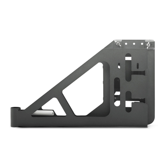
BUMPER MOUNTED TIRE CARRIER
21 + JEEP WRANGLER JL
TCJL-13
TOOLS
REQUIRED
- T8, T25 Torx Bit
- #4, #5 Allen Head Bit
- 13, 17, 18, 19mm Wrenches
- 13, 17, 18mm Socket
- 30mm Socket
- Safety Glasses
- Dremel/ Cutting Tool
- File
- Rubber Mallet
- Trim Clip Tool
WARNINGS/CAUTIONS BEFORE STARTING INSTALLATION
Before you install this kit —
instructions, warnings, cautions, and notes contained in
this installation instruction guide. Consult your vehicle
owner's manual for proper disconnection of electrical and
lifting of vehicle if required for installation of this product.
This install may require some technical skills and
knowledge of basic mechanical work. If you do not feel that
you are capable of performing this install please take this
product to a trained professional.
After reading this guide please contact us with any
questions or concerns before installing product.
Customer Service: 855-680-9595
DV8 Offroad is not responsible for any bodily injury or harm to you
or your vehicle as a result of an improper install.
6400 SYCAMORE CANYON BLVD.
RIVERSIDE, CALIFORNIA 92507
855-680-9595
WWW.DV8OFFROAD.COM
SKILL
LEVEL
- Novice/Intermediate
- 1 (you) to 2 persons
Little skill level required, you can
easily install it by yourself however,
additional help will be useful
Read and understand all
INSTALLATION
PRODUCT
TIME
- 1 Hour
Time to install this should only
take about an hour
Proper installation of this kit required knowledge of the factory
recommended procedures for removal and installation of original
equipment components. We recommend that the factory shop manual
and any special tools needed to service your vehicle be on hand during
the installation. Installation of this kit without proper knowledge of the
factory recommended procedures may affect the performance of these
components and the safety of the vehicle
• Always wear eye protection when operating power tools
Inspect all contents of this package to make sure product is not damaged
and all installation hardware has been included. If parts are missing from
kit, please be prepared to provide the following information
1. Name of purchase location
2. Bar Code on side of box
3. Date above bar code
4. Date inside box cover
NEED HELP?
MANUAL
REQUIRED
855-680-9595
Advertisement

Related Manuals for DV8 OFFROAD TCJL-13


Summary of Contents for DV8 OFFROAD TCJL-13
- Page 1 1. Name of purchase location Customer Service: 855-680-9595 2. Bar Code on side of box DV8 Offroad is not responsible for any bodily injury or harm to you 3. Date above bar code or your vehicle as a result of an improper install.
- Page 2 INSTALLATION MANUAL Begin by unpacking all items and inspecting for missing pieces or damage. If you have any concerns, please contact the company the product was purchased from. Extra hardware may be included with the product. HARDWARE INCLUDED (2) M10x25mm Bolts (3) M10x30 Countersunk bolts (2) M10 Nuts...
- Page 3 INSTALLATION MANUAL STEP 3 | Loosen the remaining hardware on the passenger side and remove the hardware on the passenger side, allowing the tire carrier to drop and rotate slightly to the passenger side. Remove the third brake light and gently set it on the bumper.
- Page 4 INSTALLATION MANUAL STEP 4 | Use a T25 torx bit to remove the two bolts securing the stud plate to the tire carrier. Then, using a rubber mallet, remove the stud plate. Use the mallet with caution, taking care not to damage the carrier or vehicle paint. 855-680-9595 NEED HELP?
- Page 5 INSTALLATION MANUAL STEP 5 | Remove the factory carrier and set it off the side. STEP 6 | Open the tailgate and use a trim clip tool to remove the plastic panel from the tail gate. Clips are located along each edge. Pull straight away from the tailgate to avoid breaking any clips.
- Page 6 INSTALLATION MANUAL STEP 7 | Remove the fin vents by pulling from the exterior, while using a trim clip tool on the interior if necessary. STEP 8 | Using a dremmel or cutting tool of choice, remove the three sided border from the fin vents.
- Page 7 INSTALLATION MANUAL STEP 9 | Use a T8 torx bit to remove the camera from the factory carrier and disconnect it by pressing the release tab on the connector. Place the camera off to the side on a soft surface being careful not to scratch/ damage it.
- Page 8 INSTALLATION MANUAL STEP 10 | Install the heim joints onto the carrier using the provided M12x50 hex bolts with hardware and provided isolators. Use a 17mm socket and 18mm wrench. 855-680-9595 NEED HELP?
- Page 9 INSTALLATION MANUAL STEP 11 | Loosely install the stopper bracket using the provided M10x25 hardware. Use a 18mm wrench and 17mm socket. STEP 12 | Install the carrier “catch” using the provided M8x45 hardware. Use a 13mm wrench and socket. 855-680-9595 NEED HELP?
- Page 10 INSTALLATION MANUAL STEP 13 | Install the provided spacer plate, followed by the bearing as shown. 855-680-9595 NEED HELP?
- Page 11 INSTALLATION MANUAL STEP 14 | Place the carrier post over the stud/bearing and ensure it is seated properly over the spacer plate. STEP 15 | Then install the race and remaining bearing as shown with the race being placed first, and the bearing on top, facing down.
- Page 12 INSTALLATION MANUAL STEP 17 | Using a 30mm socket and provided hardware, secure the tire carrier to the main support post. Be careful not to overtighten the nut, as this can lead to premature failure of the bearing. STEP 18 | Install the dust cap.
- Page 13 INSTALLATION MANUAL STEP 19 | Feed the rear back up camera wiring harness through the DV8 Tire Carrier. 855-680-9595 NEED HELP?
- Page 14 INSTALLATION MANUAL STEP 20 | Using the factory camera housing previously removed, feed the rear camera wiring harness though the rear camera housing. STEP 21 | Reconnect the rear camera harness to the rear camera. Reinstall the rear camera on to the factory camera housing using factory hardware and a T8 Torx bit.
- Page 15 INSTALLATION MANUAL STEP 22 | Using the provided M12x35 hardware, 18mm socket and 19mm wrench, secure the tire carrier to the swing arm. 855-680-9595 NEED HELP?
- Page 16 INSTALLATION MANUAL STEP 23 | Feed factory tire mount and rear camera through DV8 Tire Carrier. STEP 24 | Secure the factory rear camera/ tire mount to the DV8 Tire Carrier using the (2) factory torx head screws previously removed. Use a T25 torx bit.
- Page 17 INSTALLATION MANUAL STEP 25 | Secure the factory Rear brake light onto the DV8 Tire Carrier using the (4) factory torx head screws previously removed. Reconnect the rear brake light to factory wiring harness. 855-680-9595 NEED HELP?
- Page 18 INSTALLATION MANUAL STEP 26 | Secure th DV8 stud plate on to the DV8 Tire Carrier using the provided M10 countersunk allen head bolts and hardware with a #6 Allen bit and 17mm wrench. STEP 27 | Adjust the camera tube and secure using the provided M6 hardware with a #4 allen bit.
- Page 19 INSTALLATION MANUAL STEP 28 | Secure the heim joint to the DV8 Back Plate using the provided M12 hardware, an 18mm wrench and an 18mm socket. STEP 29 | Adjust the heim joints by turning the center connector nut. This is adjusted properly when the tail gate is closed the swing arm is parallel with the tail gate and the carrier stopper lands in the catch.
- Page 20 INSTALLATION MANUAL STEP 31 | Double check that all hardware is secure. Congratulations, The DV8 Bumper Mounted Tire Carrier installation is now complete. 855-680-9595 NEED HELP?
Need help?
Do you have a question about the TCJL-13 and is the answer not in the manual?
Questions and answers