Advertisement
Quick Links
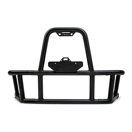
TUBE SPARE TIRE CARRIER
07-18 JEEP JK
TCJK-14
TOOLS
REQUIRED
- 12-16ft wire for license plate light
- Trim tool, ginder, hammer, punch, drill,
3/8" drill bit
- Adjustable wrench, 17mm wrench
- 7, 10, 13, 15, 17mm socket
-T50, #5, #7, #12 Allen head
- Safety Glasses
WARNINGS/CAUTIONS BEFORE STARTING INSTALLATION
Before you install this kit —
instructions, warnings, cautions, and notes contained in
this installation instruction guide. Consult your vehicle
owner's manual for proper disconnection of electrical and
lifting of vehicle if required for installation of this product.
This install may require some technical skills and
knowledge of basic mechanical work. If you do not feel that
you are capable of performing this install please take this
product to a trained professional.
After reading this guide please contact us with any
questions or concerns before installing product.
Customer Service: 855-680-9595
DV8 Offroad is not responsible for any bodily injury or harm to you
or your vehicle as a result of an improper install.
555 E QUEEN CREEK RD
CHANDLER,AZ 85286
855-680-9595
WWW.DV8OFFROAD.COM
SKILL
LEVEL
- Intermediate
- 2 person
Moderate skill level required, you
can easily install it by yourself.
Read and understand all
INSTALLATION
PRODUCT
TIME
- 4.5 Hours
Time to install this should only
take about four and a half hours.
Proper installation of this kit required knowledge of the factory
recommended procedures for removal and installation of original
equipment components. We recommend that the factory shop manual
and any special tools needed to service your vehicle be on hand during
the installation. Installation of this kit without proper knowledge of the
factory recommended procedures may affect the performance of these
components and the safety of the vehicle
• Always wear eye protection when operating power tools
Inspect all contents of this package to make sure product is not damaged
and all installation hardware has been included. If parts are missing from
kit, please be prepared to provide the following information
1. Name of purchase location
2. Bar Code on side of box
3. Date above bar code
4. Date inside box cover
NEED HELP?
MANUAL
REQUIRED
855-680-9595
Advertisement

Related Manuals for DV8 OFFROAD TCJK-14


Summary of Contents for DV8 OFFROAD TCJK-14
- Page 1 1. Name of purchase location Customer Service: 855-680-9595 2. Bar Code on side of box DV8 Offroad is not responsible for any bodily injury or harm to you 3. Date above bar code or your vehicle as a result of an improper install.
- Page 2 INSTALLATION MANUAL Begin by unpacking all items and inspecting for missing pieces or damage. If you have any concerns, please contact the company the product was purchased from. Extra hardware may be included with the product. HARDWARE INCLUDED (5) M8 Nylon Lock Nuts (5) M8 Enlarge Washers (1) M14x35mm Hexagonal (6) M8 Washers...
- Page 3 INSTALLATION MANUAL STEP 2 | Open the tailgate and use a trim clip tool to remove the trim panel on the tailgate taking care to not break the tabs. STEP 3 | Disconnect the third brake light wiring harness. Small gray plug shown in image.
- Page 4 INSTALLATION MANUAL STEP 5 | Remove the rubber tire stoppers by pulling them out. If you must use a trim clip tool, be careful not to scratch the paint. Clean surface of any dirt. STEP 6 | Use a 13mm socket to remove the (8) factory bolts securing the tire carrier to the vehicle, set the carrier off to the side.
- Page 5 INSTALLATION MANUAL STEP 7 | Before you remove any door hardware, using a bent piece of cardboard or other material, support the passenger side of the rear door so it does not fall when hinges are removed. Use a trim clip tool to remove the plastic hinge covers.
- Page 6 INSTALLATION MANUAL STEP 10 | Use a punch and hammer to knock out the hinge pin. 855-680-9595 NEED HELP?
- Page 7 INSTALLATION MANUAL STEP 11 | Separate the hinge in to two pieces. Remove the hinge pins collars. 855-680-9595 NEED HELP?
- Page 8 INSTALLATION MANUAL STEP 12 | Provided in the hardware kit are (4) .5mm and (4) 1mm nylon spacers to be used when connecting tailgate portion of the factory jeep hinge with the provided DV8 body bracket. STEP 13 | Place a 1mm spacer on each side of the factory hinge to start and insert the provided hinge pin to check side to side spacing.
- Page 9 INSTALLATION MANUAL STEP 14 | Use a (1) M10 washer, (1) M10 nylon locking nut and a 17mm socket to loosely secure the hinge pin in place. The washer will be use don the nut side of the bolt. STEP 15 | Loosely mount the completed hinge assembly on to the vehicle using the provided M8x30 Counter...
- Page 10 INSTALLATION MANUAL STEP 17 | Use a trim tool to lift the latch/handle of the tailgate up to align the vehicles body lines. Use cardboard to prop the driver side of the tailgate up and keep body lines aligned. STEP 18 | Use a trim tool to lift the hinge side of the tailgate up and align the body lines.
- Page 11 INSTALLATION MANUAL STEP 19 | With the body lines aligned on both sides, secure the factory hinge bolts using a 13mm socket. At this time secure the DV8 hinge bracket as well using a #5 Allen tool. STEP 20 | Remove the driver side tail light at this time using a Phillips head screwdriver.
- Page 12 INSTALLATION MANUAL STEP 21 | If equipped remove the factory license plate housing. Remove the license plate to gain access to the (2) upper hex head bolts securing the license plate housing. Use a 7mm socket to remove the (2) upper hex head bolts.
- Page 13 INSTALLATION MANUAL STEP 22 | Use a trim tool to pry the plastic cover away from the housing to gain access to the license plate light electrical plug. 855-680-9595 NEED HELP?
- Page 14 INSTALLATION MANUAL STEP 23 | Disconnect the license plate light electrical plug and set the cover off to the side, it will not be used with the DV8 tire carrier. STEP 24 | To gain access to the housings (2) lower mounting hex bolts, use a 15mm socket to disconnect the bumper from the bumper support on the drive side only.
- Page 15 INSTALLATION MANUAL STEP 25 | With the bumper support disconnected you can flex the bumper down enough to use a 7mm socket to remove the housings (2) lower mounting hex bolts. STEP 26 | Use a pick tool to lift up and release the (2) plastic retaining clips.
- Page 16 INSTALLATION MANUAL STEP 27 | Push the factory license plate light wiring harness back into the body of the jeep. STEP 28 | Clean off any dirt from where the license plate housing was mounted and install the provided license plate cover.
- Page 17 INSTALLATION MANUAL STEP 29 | Assemble the tire carrier cage using the provided M8 hardware and a #6 Allen tool. WE HIGHLY RECOMMEND CLEANING THESE THREADS WITH A TAP OR RUNNING THE HARDWARE THROUGH THEM PRIOR TO ASSEMBLY. These have grease in them for the coating process and can prevent easy installation during assembly.
- Page 18 INSTALLATION MANUAL STEP 30 | Sandwich the license plate bracket between the tire carrier cage and the tire spindle as shown. STEP 31 | Secure the license plate bracket and tire spindle to the tire carrier cage using the provided M8 hardware and a 13mm socket.
- Page 19 INSTALLATION MANUAL STEP 32 | With the tire carrier assembly complete attach the tire carrier to the DV8 hinge bracket. STEP 33 | Using a 12mm Allen tool and adjustable wrench, loosely secure the tire carrier to the top hinge using the provided M14x34mm bolt, Cam nut, M14 flat washer and M14 nylon lock nut.
- Page 20 INSTALLATION MANUAL STEP 34 | Using a 12mm Allen tool and adjustable wrench, loosely secure the bottom hinge using the provided M14x25mm bolt, flat washers and nylon locking nut. Use (1) washer at the top of the bolt and (1) washer on the lock nut side of the bolt. STEP 35 | Install the (2) M10 x35mm into the hinge brackets as shown.
- Page 21 INSTALLATION MANUAL STEP 37 | Install the spindle plate on the back side of the spare tire. STEP 38 | Use the T handle to secure the spare tire on to the tire carrier. 855-680-9595 NEED HELP?
- Page 22 INSTALLATION MANUAL STEP 39 | Attach the provide foam to the back of the driver side mounting bracket. STEP 40 | Attach the driver-side bracket to the tire carrier using the provided pins. 855-680-9595 NEED HELP?
- Page 23 INSTALLATION MANUAL STEP 41 | While the tire carrier is still attached to the mounting bracket (not shown in photo) close the tire carrier and lay the bracket against the body of the vehicle and mark the holes that will need to be drilled out.
- Page 24 INSTALLATION MANUAL STEP 43 | Mount the driver side tire carrier bracket using the counter sunk M8 hardware. Use a M8 flat washer and M8 nylon locking nut per M8 counter sunk M8 bolt. STEP 44 | Close the tire carrier. If adjustment is needed, turn the cam nut on the top hinge bolt to tilt the tire carrier up or down.
- Page 25 INSTALLATION MANUAL STEP 46 | Secure all other hinge bolts. Note: Do not over tighten to where the carrier becomes difficult to open and close. STEP 47 | Reinstall the driver side tail light with factory hardware and Phillips head screwdriver. 855-680-9595 NEED HELP?
- Page 26 INSTALLATION MANUAL STEP 48 | Using automotive wire, extend the license plate light harness. Route the extended license plate harness through one of the trunk drain plugs and into the vehicle over to the passenger side. We recommend using T-taps/wire taps and 18 gauge wire to extend the factory license plate wiring harness so no splicing is required.
- Page 27 INSTALLATION MANUAL STEP 51 | Continue routing the extended over and into the tire carrier cage. 855-680-9595 NEED HELP?
- Page 28 INSTALLATION MANUAL STEP 52 | Connect the extended license plate harness to the provided license plate light. Use the zip tie tabs to secure any loose wiring. STEP 53 | The tire carrier cage is equipped with (2) 1/2 inch holes to mount additional accessories such as antennas, LED whips, flags and etc.
- Page 29 INSTALLATION MANUAL STEP 54 | Reinstall any and all plastic interior trim panels. Double check that all hardware is secure. STEP 55 | Congratulations installations of the DV8 tire carrier is complete. 855-680-9595 NEED HELP?
Need help?
Do you have a question about the TCJK-14 and is the answer not in the manual?
Questions and answers