Rockwell Automation Allen-Bradley Guard master 440F-C4000D User Manual
Matguard control unit with matguard pressure sensitive safety mat system
Hide thumbs
Also See for Allen-Bradley Guard master 440F-C4000D:
- Installation instructions manual (25 pages)

Subscribe to Our Youtube Channel
Related Manuals for Rockwell Automation Allen-Bradley Guard master 440F-C4000D


Summary of Contents for Rockwell Automation Allen-Bradley Guard master 440F-C4000D
- Page 1 MatGuard Control Unit with MatGuard Pressure Sensitive Safety Mat System Catalog Numbers 440F-C4000D, 440F-C4000P User Manual Original Instructions...
- Page 2 If this equipment is used in a manner not specified by the manufacturer, the protection provided by the equipment may be impaired. In no event will Rockwell Automation, Inc. be responsible or liable for indirect or consequential damages resulting from the use or application of this equipment.
-
Page 3: Table Of Contents
Wiring ............30 Rockwell Automation Publication 440F-UM003A-EN-P - January 2024... - Page 4 Index ............53 Rockwell Automation Publication 440F-UM003A-EN-P - January 2024...
-
Page 5: About This Publication
Systems EMC Directives The safety mat system complies with the requirements of the European EMC Directive. Normal operation under interference conditions likely in industrial environments is confirmed and has been tested and certified. Rockwell Automation Publication 440F-UM003A-EN-P - January 2024... -
Page 6: Functional Safety Data
MatGuard Mat Voltage 24VDC EN 954-1 Category 3, System Response Time 35ms See user manual for further information MADE IN THE UK ISOLATE ALL POWER SUPPLIES BEFORE OPENING 83HA TYPE 1 A300 IND CONT EQ Rockwell Automation Publication 440F-UM003A-EN-P - January 2024... -
Page 7: Storage
Combinations of chemicals can have unpredictable effects. We recommend tests in such cases. Small pieces of the vinyl material are available if tests are required. Rockwell Automation Publication 440F-UM003A-EN-P - January 2024... -
Page 8: Possible Misuse
The start or restart of the machine must only be possible by a separate and deliberate action at the designated machine controls. Rockwell Automation Publication 440F-UM003A-EN-P - January 2024... -
Page 9: Additional Resources
Guard I/O module to monitor a 440F safety mat. Provides guidance on how to conduct security assessments, implement System Security Design Guidelines Reference Manual, publication Rockwell Automation® products in a secure system, harden the control system, manage user SECURE-RM001 access, and dispose of equipment. - Page 10 Preface Notes: Rockwell Automation Publication 440F-UM003A-EN-P - January 2024...
-
Page 11: Product Overview
Cable underneath the trim contact, and give all-over sensitivity. Cable underneath trim allowing the two plates to make contact giving all over sensitivity. Rockwell Automation Publication 440F-UM003A-EN-P - January 2024... -
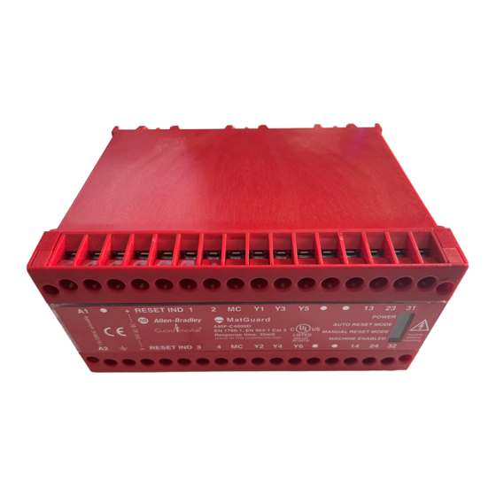
Page 12: Matguard Control Unit
Perimeter trim is used around the edges of the safety mats to hold the safety mats in place and to help prevent trip hazards. Various lengths and corner pieces are available to fit the safety mat area. Rockwell Automation Publication 440F-UM003A-EN-P - January 2024... -
Page 13: Safety Mat Functionality
Any single electrical fault in the safety mat, wiring, or safety mat manager is detected, and the MatGuard control unit outputs goes to a safe (off) state. Rockwell Automation Publication 440F-UM003A-EN-P - January 2024... -
Page 14: Matguard Control Unit Selection
115/230V AC Approximate Dimensions Figure 8 - Dimensions [mm (in.)] 440F-C4000P (Polycarbonate) 440F-C4000D 113.5 (4.5) 10 (0.39) 73 (2.9) 152 (6.0) (0.43) 130 (5.2) 75 (3.0) 4 x M4 (0.16) DIN Rail [35 (1.38)] Rockwell Automation Publication 440F-UM003A-EN-P - January 2024... - Page 15 Manual Reset/ Auto Reset Control Unit N/O PB R IND 31 32 13 14 23 24 Volt Free Aux. Contacts for Indication necessary) L1 L2 L3 Sensor Remote Reset Push Button Mats (if necessary) Rockwell Automation Publication 440F-UM003A-EN-P - January 2024...
- Page 16 24V AC/DC Supply Optional Remote Indication Unit Y1 Y2 Y3 Y4 Y5 Y6 RESET RESET L1 L2 L3 K1 AUX 110/230V AC Supply K1 AUX Remote Reset Illumination Push Button (if necessary) (if necessary) Rockwell Automation Publication 440F-UM003A-EN-P - January 2024...
-
Page 17: System Design
The position of the safety mats depends on the use case. You can use safety mats as: • Combined trip and presence sensing devices. • Presence sensing systems within a perimeter guarded area. Rockwell Automation Publication 440F-UM003A-EN-P - January 2024... -
Page 18: Combined Trip And Presence Sensing Device
IMPORTANT If the machine is designed in conformity with an existing harmonized European C type standard for that machine (which gives specific formulas or minimum distances), then these standards must be used in preference to the standards given in ISO 13855. Rockwell Automation Publication 440F-UM003A-EN-P - January 2024... -
Page 19: Safety Distance Calculations
(63 in./s) as the approach speed. T is the overall stopping time in seconds. The added 1200 mm (47.24 in.) is parameter C given in ISO 13855 and accounts for stride length and arm reach. Rockwell Automation Publication 440F-UM003A-EN-P - January 2024... -
Page 20: Presence Sensing System Within Perimeter Guarding Area
Figure 14 - Guarded Perimeter Hazard Fixed Guarding Interlocked Door (with locking) Safety Mats Rockwell Automation Publication 440F-UM003A-EN-P - January 2024... -
Page 21: Fixed Guards
Prevent access to the hazardous zone from positions that do not involve standing on the MatGuard safety mats. This restricted access requires additional angle plates and the careful position of pipework and trunking. Best practice is illustrated in Figure 15 on page Rockwell Automation Publication 440F-UM003A-EN-P - January 2024... -
Page 22: Safety Mat Pattern
The vinyl outer surface of the safety mat is sealed to resist the ingress of liquids and rated to IP67. Safety mats resist bleaches, acids, salt, and most industrial chemicals. See Table 1 on page Rockwell Automation Publication 440F-UM003A-EN-P - January 2024... -
Page 23: Wear And Damage
If access to the MatGuard control unit is required for manual reset or routine indicator observation, it must be mounted at an accessible position outside the protection zone that provides a good view of the hazard and protection zone. Rockwell Automation Publication 440F-UM003A-EN-P - January 2024... -
Page 24: Electrical Interface
(IEC 364-4-41). One pole must be earthed (negative to be earthed for DC supplies). Figure on page 25…Figure 23 on page 29 show examples of interconnections of the safety mat system. Rockwell Automation Publication 440F-UM003A-EN-P - January 2024... - Page 25 LINK MAT PLATES WHITE 13 23 Control Unit Safety Mats SENSOR MATS CONTROL UNIT Motor MOTOR N/O PB R IND 14 24 –VE Protection PROTECTION (Thermal E.G. THERMAL Cutout) CUT OUT Fuse FUSE Rockwell Automation Publication 440F-UM003A-EN-P - January 2024...
- Page 26 Contactor CONTACTOR Auxiliary AUXILIARY Control Unit Safety Mats Contacts SENSOR MATS CONTROL UNIT CONTACTS Motor 14 24 MOTOR N/O PB R IND –VE Protection PROTECTION (Thermal E.G. THERMAL Cutout) CUT OUT Fuse FUSES Rockwell Automation Publication 440F-UM003A-EN-P - January 2024...
- Page 27 WHITE Y1 Y3 Y5 13 23 Safety Mats Control Unit SENSOR MATS CONTROL UNIT Motor Reset Reset MOTOR 14 24 – RESET RESET Protection PROTECTION (Thermal E.G. THERMAL Cutout) CUT OUT Fuse FUSE Rockwell Automation Publication 440F-UM003A-EN-P - January 2024...
- Page 28 Figure 22 on page 29 Figure 23 on page 29 show both reset modes of the MatGuard safety mat system. Rockwell Automation Publication 440F-UM003A-EN-P - January 2024...
-
Page 29: Reset Modes
Figure 23 - Auto Reset Mode Relationship between actuation, reset, and output. Power to Mat Manager Actuating Force Mat Manager Safety Outputs Time 20 ms Response time Rockwell Automation Publication 440F-UM003A-EN-P - January 2024... -
Page 30: Auxiliary Output
Where wire runs are required across the floor, the 440F-T3230 wire guide provides suitable protection. Use conduit or trunking for other wire runs. Use correctly sized and tightened conduit fittings or cable glands to IP65 to maintain the sealing integrity of the control unit. Rockwell Automation Publication 440F-UM003A-EN-P - January 2024... -
Page 31: Final Details
Final Details Prepare a work schedule and drawings of the system layout and the electrical circuit. We recommend that you record and retain all measurements and calculations in the technical file for the machine. Rockwell Automation Publication 440F-UM003A-EN-P - January 2024... - Page 32 Chapter 2 System Design Notes: Rockwell Automation Publication 440F-UM003A-EN-P - January 2024...
-
Page 33: Safety Mat Installation
Sensor Mats Terminals at Control Unit The safety mat wires have a black outer covering; two have a black inner sheath and two have a white inner sheath (see Figure 24 for positions). Rockwell Automation Publication 440F-UM003A-EN-P - January 2024... -
Page 34: Unite Trim Fixing
Notch the perimeter trim completely so that any flexing of the perimeter trim does not trap the wiring. Confirm that there are no sharp edges or burrs that can damage the wires. Rockwell Automation Publication 440F-UM003A-EN-P - January 2024... -
Page 35: Control Unit Installation And Wiring
Only use a suitable ratchet type crimp tool. Crimp onto both the conductor and the insulation. Do not connect multiple wires onto one crimp. Rockwell Automation Publication 440F-UM003A-EN-P - January 2024... - Page 36 Primary Fuse 500 mA Mode set Voltage set 110V MANUAL 230V AUTO Date tick boxes N/O PB R IND 31 32 13 14 23 24 For correct installation, follow the Installation Procedure on page Rockwell Automation Publication 440F-UM003A-EN-P - January 2024...
-
Page 37: Installation Procedure
2. With 24V AC, the earthed pole of the power supply must be connected to the terminal (–ve). 4. Safety mat connections: Connect the leads from the safety mat to the terminals shown. 1=White, 2=White, 3=Black, 4=Black. Rockwell Automation Publication 440F-UM003A-EN-P - January 2024... - Page 38 Replace the lid. Secure the lid on relevant units. IMPORTANT Disconnect the machine prime mover from the final contactors so that no machine movement can take place. Rockwell Automation Publication 440F-UM003A-EN-P - January 2024...
-
Page 39: Check The Mechanical Installation
2. Check the indicators on the control unit: • Power indicator (green) illuminates • Machine-enabled indicator (green) illuminates 3. Stand on the safety mat and check that the machine-enabled indicator goes off. Rockwell Automation Publication 440F-UM003A-EN-P - January 2024... -
Page 40: Under Fault Condition
2. Check any other safety functions associated with the machine circuits that the installation of the safety mat system can affect. You must have an existing procedure for these tests. 3. Isolate the machine power supply at the source. Rockwell Automation Publication 440F-UM003A-EN-P - January 2024... -
Page 41: Functional Checkout
5. If any type of muting system is installed, check that the safety mat system is muted only during non-hazardous parts of the operating cycle and that any mute indicators operate correctly. 6. Test the emergency stop function of the machine. Rockwell Automation Publication 440F-UM003A-EN-P - January 2024... - Page 42 Chapter 3 Installation Notes: Rockwell Automation Publication 440F-UM003A-EN-P - January 2024...
-
Page 43: Pre-Operation Checks
Verify that all personnel understand that no additional coverings, boards, plates, or planks can be on the sensor mat during machine operation. Rockwell Automation Publication 440F-UM003A-EN-P - January 2024... - Page 44 Chapter 4 System Operation Notes: Rockwell Automation Publication 440F-UM003A-EN-P - January 2024...
-
Page 45: Safety Mat Cleaning
We recommend thorough inspections twice a year or after damage. Test Contact your local Allen-Bradley distributor or Rockwell Automation sales office for information on an authorized testing service. A person who is competent in electrical and mechanical engineering must perform the tests. -
Page 46: Dismantle And Disposal
2. If the machine-enabled indicator on the safety mat control unit is off, take the following actions: a. Check that the power indicator is illuminated. If it is not, check the power supply to the safety mat control unit. Rockwell Automation Publication 440F-UM003A-EN-P - January 2024... -
Page 47: Symptom: No Stop
Record the replacement in the inspection log. If either fuse blows immediately or requires early replacement, contact your local Allen-Bradley distributor or Rockwell Automation sales office. 3. If the machine-enabled indicator on the safety mat control unit is off and the power indicator is on, there is a fault in the system. -
Page 48: Repair
440F-T2015 1000 x 1000 39.4 x 39.4 440F-M2020BYNN 440F-T2020 1000 x 1200 39.4 x 47.2 440F-M2024BYNN 440F-T2024 1000 x 1250 39.4 x 49.2 440F-M2025BYNN 440F-T2025 1000 x 1500 39.4 x 59.1 440F-M2030BYNN 440F-T2030 Rockwell Automation Publication 440F-UM003A-EN-P - January 2024... - Page 49 IMPORTANT After maintenance or repair operations, it is important that all edging trims, fastenings, and cable protection are correctly refitted. Failure to do this step, the use of non-approved parts, or modifications can prevent the safety mat system from achieving its specified performance. Rockwell Automation Publication 440F-UM003A-EN-P - January 2024...
-
Page 50: Service
Rockwell Automation sales office. Record of Routine Inspection and Test on page 45 (weekly) Date: Inspected By: Comments: Record of Thorough Examination and Test on page 45 (every 6 months) Date: Inspected By: Comments: Rockwell Automation Publication 440F-UM003A-EN-P - January 2024... -
Page 51: Matguard Control Units
W = 152 mm (5.98 in.) W = 130 mm (5.12 in.) 32-way DIN rail Weight 0.88 kg (1.94 lb) 0.92 kg (2.03 lb) (1) 110V setting also allows use at 100V ±10% Rockwell Automation Publication 440F-UM003A-EN-P - January 2024... -
Page 52: Sensor Mat
Yellow Operating temperature range -10…+55 °C (14…131 °F) Storage temperature range -40…+70 °C (-40…+158 °F) The system that is composed of interconnected sensor mats and control unit meets the requirements of ISO 13849-1. Rockwell Automation Publication 440F-UM003A-EN-P - January 2024... -
Page 53: Index
40 product overview 11 fault finding 46 publication about 5 fixed guards 21 functional checkout 41 repair 48 reset mode general description 11 auto 39 resources 9 routine inspection 45 hazard 17 Rockwell Automation Publication 440F-UM003A-EN-P - January 2024... - Page 54 43 all types 40 dual-channel 40 single-channel 40 test 45 thorough examination 45 trim perimeter 12 uniting 12 trip sensing device 18 under fault condition 40 unexpected stoppage 47 uniting trim active 12 Rockwell Automation Publication 440F-UM003A-EN-P - January 2024...
- Page 55 MatGuard Control Unit with MatGuard Pressure Sensitive Safety Mat System User Manual Rockwell Automation Publication 440F-UM003A-EN-P - January 2024...
- Page 56 At the end of life, this equipment should be collected separately from any unsorted municipal waste. Rockwell Automation maintains current product environmental compliance information on its website at rok.auto/pec. Allen-Bradley, CompactBlock, expanding human possibility, Guard I/O, GuardLogix, Guardmaster, MatGuard, POINT Guard I/O, Rockwell Automation, and SmartGuard are trademarks of Rockwell Automation, Inc.
Need help?
Do you have a question about the Allen-Bradley Guard master 440F-C4000D and is the answer not in the manual?
Questions and answers