Walker Edison BQSPIN Assembly Instructions Manual
Hide thumbs
Also See for BQSPIN:
- Assembly instructions manual (14 pages) ,
- Assembly instructions manual (14 pages) ,
- Manual (42 pages)
Advertisement
Quick Links
Advertisement

Subscribe to Our Youtube Channel
Related Manuals for Walker Edison BQSPIN


Summary of Contents for Walker Edison BQSPIN
- Page 1 Item #: BQSPIN Assembly Instructions Revised 08/2023 - V6 P. 1...
- Page 2 A Phillips head screwdriver is required for the assembly of this Product. P. 2...
- Page 3 Description Description Part# Part# Spindle 14 pcs 04 pcs Feet 26 pcs Right side rail 01 pcs Slats 02 pcs 01 pcs Bracket Left side rail Top rail 01 pcs Middle foot support 03 pcs 01 pcs 01 pcs Bottom rail Cross bar Support beam 02 pcs...
- Page 4 ø7,0*70mm 14 pcs Bolt 94 pcs ø3.5*30mm Screw 08 pcs ø7,0*50mm Bolt 14 pc ø10*40mm Wood dowel 04 pc ø6*30mm Wood dowel Hex key 02 pc Spacer 02 pcs 82 mm 10 pcs ø1/4*40mm Bolt 10 pcs ø1/4 Union Screw 28 pcs ø4.0*16mm Screw...
- Page 5 Ø10x40mm Insert wood dowels (E) into parts 5,28,29 Insert wood dowels (F) into parts 13 Ø6x30mm Attach center bar support (R) into parts 28,29 with screw (P) using a Phillips head screwdriver (not included). Ø4x16mm Step 3 Ø7x70mm Attach middle foot support 23 to cross bar 24 with screw (A) using the hex key (J).
- Page 6 Step 4 Connect parts 20,21 to parts 28,29. Step 5 Secure parts 20,21 to parts 28,29 with screws (A), using the hex key (J). Ø7x70mm P. 6...
- Page 7 Step 6 Connect parts 28,29 to parts 20,21 with screw B, using a Phillips head screwdriver (not included). Ø3,5x30mm Step 7 Attach feet 15 to Right side rail and Left side rail 20,21 using screw (M) and Union Screw (N). Union Screw (N) should be on the inside of the bed frame, with screw (M) on the outside of the feet.
- Page 8 Step 8 Ø3,5x30mm Secure feet to Right side rail and Left side rail, with screw (B) using a Phillips head screwdriver (not included). Step 9 P P P Attach the metal connector plate (Q) to the 2 corners of the bed with screw (P), using a Phillips head screwdriver Ø4x16mm (not included).
- Page 9 Step 10 Secure part 24 to center bar support (R) with screw (P) using a Phillips head screwdriver (not included). Ø4x16mm Step 11 Start With Space Ø3,5x30mm Place part 2 onto parts 20,24 and parts 21,24. Use part (L) to space part 2 from the end and secure with screw (B) using a Phillips head screwdriver.
- Page 10 Step 12 Ø3,5x30mm Connect parts 5 to part 7. Note the drawing for location of pocket hole. Secure parts 5 to part 7 with the screw (B) using a Phillips head screwdriver (not included). Step 13 Ø7x50mm Attach parts 13 to part 6 with the bold D using a hex key (J). P.
- Page 11 Step 14 Start at one end of the headboard. Fit large spindle 13 into part 5 and secure with screw (D) using a hex key (J). Ø7x50mm Step 15 Ø3,5x30mm Insert the Spindle 1 underneath and the Screw (B) to connect to Part 6 using a Phillips head screwdriver (not included). P.
- Page 12 Step 16 Insert Headboard slat 14 on part 7, with screws (P), using a Phillips head screwdriver (not included). Ø4x16mm Step 17 Insert screws (B) in the spindles 1 using a Phillips head screwdriver (not included). Ø3,5x30mm P. 12...
- Page 13 Step 18 Insert Wood Dowel 2x (E) in part 14. Ø10x40mm Step 19 First make sure Wood dowel inserted on the frame 7 is aligned Align dowels in part 7 with the dowel holes in part 29 and press together firmly. P.
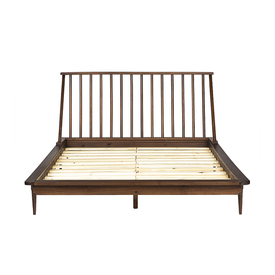
- Page 14 Step 20 Join the part 7 to parts 29 and 5 with screw (M) and union screw (N) using hex key (J) Ø1/4x40mm Step 21 Assembly Complete! P. 14...
Need help?
Do you have a question about the BQSPIN and is the answer not in the manual?
Questions and answers