Table of Contents
Advertisement
Available languages
Available languages
Quick Links
Advertisement
Table of Contents

Subscribe to Our Youtube Channel
Related Manuals for Stalgast 721121


Summary of Contents for Stalgast 721121
- Page 1 Maszynka do mielenia mięsa Fleischwolf Meat Mincer 721121 721124 · Instrukcja obsługi - Instrukcja oryginalna Bedienungsanleitung - Übersetzung der Originalbedienungsanleitung Instruction manual - Translation of the original manual...
-
Page 2: Instrukcje Bezpieczeństwa
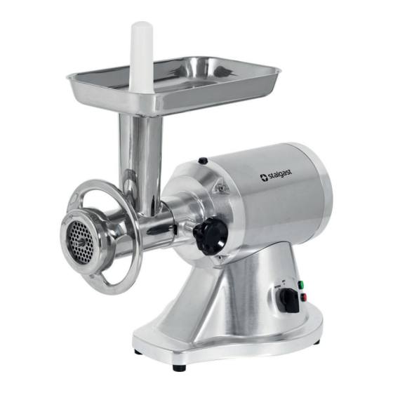
Z tego względu zdjęcia i rysunki w poniższej instrukcji mogą różnić się od zakupionego urządzenia. Instrukcja obsłu- gi każdego urządzenia zawierająca aktualne zdjęcia i rysunki, dostępna jest na stronie internetowej www.stalgast.com w zakładce „pliki do pobrania” przy opisie produktu. - Page 3 4. BUDOWA a. Włącznik b. Pokrętło blokady c. Obudowa silnika d. Sprzęgło e. Popychacz produktu f. Tacka g. Głowica h. Wał ślimakowy i. Nożyk j. Tarcza grubo mieląca k. Tarcza średnio mieląca l. Nakrętka 5. MONTAŻ 5.1. Instalacja do źródeł zasilania Urządzenie należy podłączyć...
- Page 4 Przed podłączeniem urządzenia do źródła zasilania należy upewnić się, że wyłącznik urządzenia jest ustawiony w pozy- cji wyłączonej - off. 6.5. Montaż 721121 • Umieścić Głowicę na Sprzęgle silnika • Trzymając Głowicę jedną ręką dokręcić Pokrętło blokady w kierunku zgodnym z kierunkiem obrotu wskazówek zegara.
-
Page 5: Czyszczenie I Konserwacja
• Rozcieńczalniki i preparaty zawierające benzynę mogą uszkodzić lub zmienić kolor powierzchni urządzenia. Niewielka ilość oleju spożywczego nałożona po umyciu i wysuszeniu urządzenia na elementy, h~,k zapewni odpowiednie ich smarowanie. 8. LISTA CZĘŚCI ZAMIENNYCH 8.1. 721121 1. Blokada sita 2. Ślimak 3. Tacka 4. Popychacz 5. Podkładka... -
Page 6: Deklaracja Zgodności
11. DEKLARACJA ZGODNOŚCI Producent z pełną odpowiedzialnością deklaruje, że: nazwa: Maszynka do mielenia mięsa model: 721121, 721124 Spełnia zasadnicze wymagania: • dyrektywy maszynowej MD 2006/42/EC, • dyrektywy niskonapięciowej LVD 2014/35/UE •... -
Page 7: Technische Daten
Wir danken Ihnen für den Kauf unseres Produktes. Vor der ersten Inbetriebnahme lesen Sie sich bitte sorgfältig diese Bedienungsanleitung durch. Jegliches Kopieren dieser Bedienungsanleitung ohne Zustimmung des Herstellers ist ver- boten. Die Bilder und Zeichnungen wurden anschaulich dargestellt und können von Ihrem Gerät abweichen. HINWEIS: Die Bedienungsanleitung soll an einem sicheren und für das Personal allgemein zugänglichen Platz aufbe- wahrt werden. -
Page 8: Montage
4. AUFBAU a. ON/OFF-Schalter b. Blockade-Knebelgriff c. Motorgehäuse d. Kupplung e. Stößel f. Fülltablett g. Wendelgehäuse h. Wendel i. Schneidmesser j. Lochscheibe mit dicken Bohrungen k. Lochscheibe mit mittelgroßen Bohrun- l. Verschluss 5. MONTAGE 5.1. Anschluss an die Stromversorgungsquelle Um das Gerät ans Stromnetz anzuschließen, soll man den Stecker in die Steckdose einstecken. Die Steckdose sollte geerdet sein und über einen Fehlerstromschutzschalter verfügen.. - Page 9 6.4. Vor der ersten Inbetriebnahme Alle Bestandteile des Fleischwolfs (mit Ausschluss der Elemente, die einen direkten Kontakt mit Strom haben d.h. a, b, c und d) sind in warmem Wasser mit Seife zu reinigen. Vor dem Anschluss an die Stromversorgungsquelle ist sicherzustellen, dass sich der Geräteschalter in der Off-Position befindet (ausgeschaltet ist).
-
Page 10: Reinigung Und Wartung
• Es ist untersagt, das Gerät erneut einzuschalten. Den Umschalter in die Position REVERSE – Rückwärtsgang drehen, um Knochen oder andere zu Verstopfungen führen- Reinigung und wartung den Produkte zu entfernen, Das Gerät reinigen (S. „ “ Pkt. 7) 6.8. Not-Aus / Stromausfall Der Fleischwolf ist mit einer Notabschaltung und einem Schutz gegen das Wiedereinschalten des Motors nach einem Stromausfall ausgestattet. -
Page 11: Garantie
Garantiesiegel gebrochen oder die Reparatur selbst durchgeführt wird. 11. KONFORMITÄTSERKLÄRUNG Der Hersteller erklärt mit voller Verantwortung, dass: Name: Fleischwolf Modell: 721121, 721124 die grundlegenden Anforderungen erfüllt: • die Maschinenrichtlinie MD 2006/42/EG, • die Niederspannungsrichtlinie LVD 2014/35/EU • die EMV-Verträglichkeitsrichtlinie 2014/30/EU, •... -
Page 12: Safety Instructions
Rubber feet prevent the device from moving and reduce vibration and mix noise during operation. 2.1. Unauthorized use Do not grind hard foods such as nuts, bones, seeds, etc. Do not grind hard, fibrous products such as: ginger. 3. TECHNICAL SPECIFICATION Model 721121 721124 Voltage 230 V 230 V Power... -
Page 13: Installation
Switch Locking knob Motor housing Drive shaft coupling Food pusher Hopper plate Head / Grinding unit Feed screw Cutting blade Cutting plate - coarse Cutting plate - medium Fastening nut 5. INSTALLATION 5.1. Connection to the power supply The appliance must be connected to the power source by means of a plug. The socket should be properly earthed and equipped with a differential current protection device 5.2. Positioning of the appliance Position the appliance on a level and stable surface. - Page 14 Before connecting the appliance to the power supply, make sure that the appliance switch is in the Off position 6.5. Assembly loosen 721121 • Connect the Grinding unit to the machine’s Drive shaft coupling • Holding the Grinding unit with one hand, place the Locking knob in the hole on the side of the Motor housing and ti- ghten it clockwise.
-
Page 15: Cleaning And Maintenance
• Thinners and preparations containing extraction naphtha may damage or change colour of the surfaces of the ap- pliance A small amount of cooking oil applied to the elements of the appliance (h-k) after washing and drying them ensures proper lubrication. 8. LIST OF SPARE PARTS 8.1. 721121 1. Screen lock 2. Auger 3. Tray 4. Pusher 5. Washer... -
Page 16: Warranty
11. DECLARATION OF CONFORMITY The manufacturer declares with full responsibility that: name: meat mincer model: 721121, 721124 Meets the essential requirements: • MD 2006/42/EC machinery directive, • LVD low voltage directive 2014/35/EU • EMC compatibility directive 2014/30/EU, •... - Page 17 Stalgast Sp. z o.o. Plac Konesera 9, Budynek O, 03-736 Warszawa tel.: 22 517 15 75 fax: 22 517 15 77 www.stalgast.com email: stalgast@stalgast.com • DE • • EN • • FR • ES • Stalgast GmbH Tel.: +48 22 509 30 77 Tel.: +48 22 509 30 55...
Need help?
Do you have a question about the 721121 and is the answer not in the manual?
Questions and answers