Table of Contents
Advertisement
™
Table of Contents
Section Code
Section
1
1
1
1
1
1
Connectivity
1
1
1
1
1
1
Demonstration Mode/Studio Mode
1
Replacement Procedure Skill Level
Mechanical Procedures
2
Belt Tension Adjustment
Part Replacement
3
6
Data Cable in the Mast
7
Drive Belt
8
9
16
17
™
Nautilus
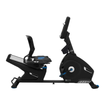
R628 Recumbent Bike Service Manual
™
®
®
ORIGINAL DOCUMENT - ENGLISH VERSION ONLY
Page Number
®
®
1
Service Manual
2
3
3
5
5
6
6
7
10
13
15
16
16
17
20
28
31
33
37
59
61
®
8016790.091519.A
Advertisement
Table of Contents

Related Manuals for Nautilus R628


Summary of Contents for Nautilus R628
-
Page 1: Table Of Contents
™ Nautilus R628 Recumbent Bike Service Manual Service Manual 8016790.091519.A ™ ™ Table of Contents Section Code Section Page Number Important Safety Instructions Safety Warning Labels and Serial Number Earthing Instructions Leveling the Machine Moving the Machine Connectivity Heart Rate Chest Strap Battery Replacement... -
Page 2: Important Safety Instructions
Do not try to do heavy or awkward steps on your own. • If replacement parts are necessary, use only genuine replacement parts and hardware supplied by Nautilus. Failure to use genuine replacement parts can cause a risk to users, keep the machine from operating correctly and void the warranty. -
Page 3: Safety Warning Labels And Serial Number
Safety Warning Labels and Serial Numbers WARNING • Keep hands and feet away. Product Serial Number Reading the Product Specification Decal Manufacture Date Code: YYWW The Manufacture Date on the Product Specification Decal is a date code: YY/WW (year/week). Earthing Instructions This product must be electrically earthed. - Page 4 When the machine is used in a Studio environment, we recommend that the Pedals be replaced every year to maintain maximum user safety and performance. Only use replacement Pedals available from Nautilus. Other brands of Pedals may not be designed...
-
Page 5: Leveling The Machine
Leveling the Machine Levelers are found on each side of the Rear Stabilizer and on the Frame Rail. On the Rear Stabilizer, turn the stabilizer foot to adjust. Do not adjust the levelers to such a from the machine. Injury to you or damage to the machine can occur. -
Page 6: Heart Rate Chest Strap Battery Replacement
® your results and share with friends and family. 1. Download the free Software App, named Nautilus Trainer™. The software app is available on the App Store and Google Play™. For a complete list of supported devices, review the software app on the App Store or Google Play™. -
Page 7: Troubleshooting
Troubleshooting Condition/Problem Things to Check Solution No display/partial display/ Check electrical (wall) Make sure unit is plugged into a functioning wall outlet. unit will not turn on outlet Check connection at front Connection should be secure and undamaged. Replace power of unit cord or connection at unit if either are damaged. - Page 8 Condition/Problem Things to Check Solution Check magnet position Magnet should be in place on pulley. (requires shroud removal) Check Speed Sensor Speed sensor should be aligned with magnet and connected to (requires shroud removal) data cable. Realign sensor if necessary. Replace if there is any damage to the sensor or the connecting wire.
- Page 9 Contact appsupport@nautilus.com (if inside US/Canada) or your local distributor (if outside US/Canada) for further assistance. Workout results not post- Sync accounts From the Menu icon on the Nautilus Trainer™ App, select the ing from Nautilus Trainer Sync to MyFitnessPal or Under Armour Connected Fitness.
-
Page 10: Console Service Mode
Console Setup Mode The Console Setup Mode lets you input the date and time, set the units of measurement to either English or Metric, Hold down the PAUSE/END button and Up Arrow button together for 3 seconds while in the Power-Up Mode to go into the Console Setup Mode. - Page 11 If correct, “RTC PASS” will be displayed. If not correct, “RTC FAIL” will be displayed. Place hands on heart rate grips. CHR = [contact heart rate] will be displayed. Turn on wireless transmitter. WHR = [wireless heart rate] will be displayed. the correct order.
- Page 12 Button test sequence If the display shows an incorrect function, the overlay on the Console may be incorrect for that model. If the display within limits. If BLE module communication is valid and programmed, “PASS” will be displayed. If not correct, “BLE FAIL” will be displayed. setup, user records and workout records will be reset to defaults.
-
Page 13: Maintenance Parts Exploded View
Maintenance Parts Exploded View Console Stabilizer, Front Drive Pulley Console Mast Transport Wheel Drive Belt Water Bottle Holder Pedals Speed Sensor Magnet (8) Seat Back Shroud, Right RPM Sensor Top Cap Shroud, Upper GG Power Inlet/Power Switch Seat Frame Assembly Shroud, Left Power Cord Seat Bottom... -
Page 14: Mcb Watts
Electrical Layout NLS U628/R628 Wiring Diagram Wireless Heart Rate Module Console Resistance Resistance Contact Down Down Heart Rate HR cable, 3Pin (CHR) sensor HR cable, 4Pin I/O (Data) cable, 6Pin Electromagnet EMS Cable, 2Pin Watts/ MCB, DC In Watts cable,... -
Page 15: Ems Engine
Motor Control Board (MCB), Watts I/O cable (to Console) Watts/DC In RPM sensor cable cable cable EMS Engine assembly EMS MCB Watts assembly EMS MCB cable (line and neutral) Watts/DC In cable EMS cable Potentiometer EMS MCB cable (line and neutral) - Page 16 Demonstration Mode Demonstration Mode is a feature on newer versions of the Console. It educates an observer about the console in a trade show or retail environment. During Demonstration Mode, the Console will display each workout Program for 4 seconds from a specific point of the workout.
- Page 17 Do not try to do heavy or awkward steps on your own. • If replacement parts are necessary, use only genuine replacement parts and hardware supplied by Nautilus. Failure to use genuine replacement parts can cause a risk to users, keep the machine from operating correctly and void the warranty.
- Page 18 NOTICE: It is necessary to remove the Shrouds for this procedure. Refer to the “Replace the Shrouds” procedure. Disconnect all power to the machine before you service it. Figure 1 - R628 left side 1. Remove the Top Shroud, Left Shroud and Right Shroud from the Main Unit.
- Page 19 R628 left side wrench and a 17mm wrench to loosen the Tensioner Assembly Hardware (A) that attaches the Tensioner Assembly to the EMS Engine bracket. Tensioner Note: Tensioner outside and turn the nut from the inside. pulley 4. Adjust the angle of the Belt Tensioner arm as necessary to adjust the tension.
- Page 20 Do not try to do heavy or awkward steps on your own. • If replacement parts are necessary, use only genuine replacement parts and hardware supplied by Nautilus. Failure to use genuine replacement parts can cause a risk to users, keep the machine from operating correctly and void the warranty.
- Page 21 Disconnect all power to the machine before you service it. 1. Press the edges of the Console Pivot Shroud to disen- gage the tabs from the Console. Remove the Console Pivot Shroud and set it safely aside. 2. Remove screws that attach Console to the Mast. Care- 3.
- Page 22 Do not try to do heavy or awkward steps on your own. • If replacement parts are necessary, use only genuine replacement parts and hardware supplied by Nautilus. Failure to use genuine replacement parts can cause a risk to users, keep the machine from operating correctly and void the warranty.
- Page 23 Disconnect all power to the machine before you service it. Note: Your machine may not match the image. For reference only. 1. Remove screws that attach Console to the Mast. 2. Disconnect the Data Cable, Heart Rate Cable and Resistance Cable from the back of the Console. Set the Console and screws safely aside for reassembly.
- Page 24 Do not try to do heavy or awkward steps on your own. • If replacement parts are necessary, use only genuine replacement parts and hardware supplied by Nautilus. Failure to use genuine replacement parts can cause a risk to users, keep the machine from operating correctly and void the warranty.
- Page 25 1. Loosen and remove the old Pedals. Set them safely aside for reassembly. Note: The Left Pedal is reverse-threaded. Orientation is based from a seated position on the bike. The Left Pedal has an “L”, the Right Pedal an “R”. (C).
- Page 26 Thread the Crank Puller into the Crank Arm (B). When the Crank Puller is in the correct position, only 1-2 threads on the outer portion (CP2) of the Crank Puller should show. Note: Be sure the end of the Bolt (CP1) of the Crank use.
- Page 27 Installation is the reverse procedure. Installation does not require the use of the crank puller. Be sure the Crank Arms are connected at 180° from each other. To reinstall the Pedals, carefully align the threads and hand tighten to prevent cross-threading. Then tighten fully with pedal wrench.
- Page 28 R628 Bike ™ ™ ™ NOTICE: This document provides instructions for the replacement of the Data Cable in the Console Mast on the Nautilus ™ R628 Recumbent Bike. If you need assistance, please contact Customer Service (if purchased in US/Canada) or your local distributor (if purchased outside This icon means a potentially hazardous situation which, if not avoided, could result in death or serious injury.
- Page 29 Disconnect all power to the machine before you service it. Note: Your machine may not match the image. For reference only. 1. Remove screws that attach Console to the Mast. 2. Disconnect the Data Cable, Heart Rate (HR) Cable and Resistance Cable from the back of the Console.
- Page 30 5. Tie the length of string to the end (A) of the Data Cable at the base of the Mast. Hold the other end of the Data Cable (B) and carefully pull it out of the Mast so that the string the old Data Cable and discard the old cable.
- Page 31 Do not try to do heavy or awkward steps on your own. • If replacement parts are necessary, use only genuine replacement parts and hardware supplied by Nautilus. Failure to use genuine replacement parts can cause a risk to users, keep the machine from operating correctly and void the warranty.
- Page 32 NOTICE: Disconnect all power to the machine before you service it. Carefully remove the Shrouds. Refer to the “Replace the Shrouds” procedure in this manual. Slowly turn the Drive Pulley (A) backward and carefully Remove the old Drive Belt (B) after noting how to properly route the new Belt.
- Page 33 Do not try to do heavy or awkward steps on your own. • If replacement parts are necessary, use only genuine replacement parts and hardware supplied by Nautilus. Failure to use genuine replacement parts can cause a risk to users, keep the machine from operating correctly and void the warranty.
- Page 34 Disconnect all power to the machine before you service it. Carefully remove the Shrouds. Refer to the “Replace the Shrouds” procedure in this manual. R628 right side view Observe the EMS Cable routing from the EMS Motor Control Board (MCB) Watts assembly to the EMS Engine assembly.
- Page 35 R628 left side view Slowly turn the Drive Pulley (B) backward and carefully ease the Drive Belt (C) to the outside to remove it from the Flywheel Pulley (D) and Tensioner Assembly pulley (E). screws and washers (with arrows) that secure the EMS Engine to the Frame.
- Page 36 13. Put the Right Shroud in position and reinstall the Right Crank Arm. Installation does not require the use of the crank puller. Note: Before fully attaching the Shrouds, check the belt tension. Refer to the “Belt Tension Adjustment” procedure. 14.
- Page 37 Do not try to do heavy or awkward steps on your own. • If replacement parts are necessary, use only genuine replacement parts and hardware supplied by Nautilus. Failure to use genuine replacement parts can cause a risk to users, keep the machine from operating correctly and void the warranty.
- Page 38 Disconnect all power to the machine before you service it. Note: Your machine may not match the image. For reference only. 1. Remove screws that attach Console to the Mast. 2. Disconnect the Data Cable, Heart Rate (HR) Cable and Resistance Cable from the back of the Console.
- Page 39 5. Tie the length of string to the end (A) of the HR/ Resistance Cable Assembly at the base of the Mast. Hold the other end of the HR/Resistance Cable Assembly (B) and through the length of the Mast. Untie the string from the old HR/Resistance Cable Assembly and discard the old cables.
- Page 40 Do not try to do heavy or awkward steps on your own. • If replacement parts are necessary, use only genuine replacement parts and hardware supplied by Nautilus. Failure to use genuine replacement parts can cause a risk to users, keep the machine from operating correctly and void the warranty.
- Page 41 NOTICE: Disconnect all power to the machine before you service it. Carefully remove the Shrouds. Refer to the “Replace the Shrouds” procedure in this manual. Observe the cable routing from the EMS Motor Control Board (MCB) Watts assembly on your machine. •...
- Page 42 4. Carefully remove the EMS MCB Watts cover. EMS MCB Watts - back left view NOTICE: cable Watts/ 5. Disconnect the cables from the MCB Watts assembly after DC In cable noting their locations. Note: Be sure to note where all cables attach for re-assembly. EMS MCB cable EMS MCB...
- Page 43 8. Make sure that the blue potentiometer on the new MCB Watts has the same setting as the old MCB Watts cable potentiometer. The indicated dots on the white adjuster should be aligned to the same position as the old MCB Watts potentiometer.
-
Page 44: Heart Rate/Resistance Cable Assembly In The Mast
NLS U628/R628 Wiring Diagram Wireless Heart Rate Module Console Resistance Resistance Contact Down Down Heart Rate HR cable, 3Pin (CHR) sensor HR cable, 4Pin I/O (Data) cable, 6Pin Electromagnet EMS Cable, 2Pin Watts/ MCB, DC In Watts cable, 4Pin Sensor... - Page 45 Do not try to do heavy or awkward steps on your own. • If replacement parts are necessary, use only genuine replacement parts and hardware supplied by Nautilus. Failure to use genuine replacement parts can cause a risk to users, keep the machine from operating correctly and void the warranty.
- Page 46 1. Loosen and remove the old Pedals. Discard the old Pedals. Note: The Left Pedal is reverse-threaded. Orientation is based from a seated position on the bike. The Left Pedal has an “L”, the Right Pedal an “R”. 2. Install the new Pedals. Carefully align the threads and hand tighten to prevent cross-threading.
- Page 47 Do not try to do heavy or awkward steps on your own. • If replacement parts are necessary, use only genuine replacement parts and hardware supplied by Nautilus. Failure to use genuine replacement parts can cause a risk to users, keep the machine from operating correctly and void the warranty.
- Page 48 NOTICE: It is necessary to remove the Shrouds for this procedure. Refer to the “Replace the Shrouds” procedure. Disconnect all power to the machine before you service it. Carefully remove the Left and Right Shrouds. Refer to the “Replace the Shrouds” procedure in this manual. Back cover Loosen and remove the indicated screw from the Power Inlet assembly to release the back cover.
- Page 49 Do not try to do heavy or awkward steps on your own. • If replacement parts are necessary, use only genuine replacement parts and hardware supplied by Nautilus. Failure to use genuine replacement parts can cause a risk to users, keep the machine from operating correctly and void the warranty.
- Page 50 NOTICE: It is necessary to remove the Shrouds for this procedure. Refer to the “Replace the Shrouds” procedure. Disconnect all power to the machine before you service it. U628 - right side view D (X8) Ziptie RPM Sensor cable connection NOTICE: R628 - right side view NOTICE: D (X8) RPM Sensor NOTICE: cable connection Note: Final Inspection...
- Page 51 Do not try to do heavy or awkward steps on your own. • If replacement parts are necessary, use only genuine replacement parts and hardware supplied by Nautilus. Failure to use genuine replacement parts can cause a risk to users, keep the machine from operating correctly and void the warranty.
- Page 52 Disconnect all power to the machine before you service it. To remove only the Seat Back, start at Step 3. Using a #2 Phillips Screwdriver, loosen and remove the hardware that attaches the padded Seat Bottom to the Seat Frame Assembly. Set the hardware safely aside for reassembly.
- Page 53 ware that attaches the Seat Adjustment Handle to the seat slider assembly. Remove the Seat Adjustment Handle. Set the hardware and Seat Adjustment Handle safely aside. Carefully remove the Top Cap from the seat slider bracket, and disconnect the Resistance and Heart Rate Cables.
- Page 54 Do not try to do heavy or awkward steps on your own. • If replacement parts are necessary, use only genuine replacement parts and hardware supplied by Nautilus. Failure to use genuine replacement parts can cause a risk to users, keep the machine from operating correctly and void the warranty.
- Page 55 Disconnect all power to the machine before you service it. Using a #2 Phillips Screwdriver, loosen and remove the hardware that attaches the padded Seat Bottom to the Seat Frame Assembly. Set the hardware safely aside for reassembly. Remove the Seat Bottom from the Seat Frame Assembly and set it safely aside.
- Page 56 ware that attaches the Seat Adjustment Handle to the seat slider assembly. Remove the Seat Adjustment Handle. Set the hardware and Seat Adjustment Handle safely aside. Carefully remove the Top Cap from the seat slider bracket, and disconnect the Resistance and Heart Rate Cables.
- Page 57 10. Using a #2 Phillips screwdriver, loosen and remove the screw that secures the front Seat Rail End Cap. Bend the edges of the rear Seat Rail End Cap to disengage the inside tabs from the Main Assembly, and remove. Set the hardware and Caps safely aside for reassembly.
- Page 58 14. Installation is the reverse procedure. Note: Self-tapping screws attach the Shrouds to the Frame. NOTICE: Be sure not to crimp any cables. Be sure the tabs in the Top Shroud snap into the Main Assembly. it. Be sure the cables are tucked inside the Top Cap.
-
Page 59: Seat Recline Shock Assembly
Do not try to do heavy or awkward steps on your own. • If replacement parts are necessary, use only genuine replacement parts and hardware supplied by Nautilus. Failure to use genuine replacement parts can cause a risk to users, keep the machine from operating correctly and void the warranty. - Page 60 1. Using a #2 Phillips Screwdriver, remove the 2 screws (*) that secure the Shock Shroud. Turn the Shock Shroud to (B) that attaches the Shock Assembly (A) and the Seat Recline Arm (C) on the Seat Back. Set it safely aside. 3.
- Page 61 Do not try to do heavy or awkward steps on your own. • If replacement parts are necessary, use only genuine replacement parts and hardware supplied by Nautilus. Failure to use genuine replacement parts can cause a risk to users, keep the machine from operating correctly and void the warranty.
- Page 62 Disconnect all power to the machine before you service it. To remove the Main Shrouds, start at Step 1. To remove only the Rear Shrouds, go to Step 10. 3. Thread the Crank Puller into the Crank Arm (B). When the Crank Puller is in the correct position, only 1-2 threads on the outer portion (CP2) of the Crank Puller should show.
- Page 63 6. Bend the edges of the Top Shroud to disengage the inside tabs from the Main Assembly, and slide the Top Shroud up the Mast. (indicated) from the Mast. Gently pull the Mast out and disconnect the cables. Set the hardware, Mast and Console, and Top Shroud safely aside for reassembly.
- Page 64 8. Using a #2 Phillips screwdriver, remove the 4 screws (indicated) that secure the Left Main Shroud. Remove the the Left Main Shroud. Set the hardware and Shroud safely aside for reassembly. NOTICE: Be sure not to crimp any cables. 9.
-
Page 65: Shrouds
12. Using a #2 Phillips screwdriver, remove the screws that secure the Right Rear Shroud. Slowly remove the Right Shroud. Set the hardware and Right Shroud safely aside for reassembly. 13. Installation is the reverse procedure. Put the Left Shroud Note: Self-tapping screws attach the Shrouds to the Frame. - Page 66 Do not try to do heavy or awkward steps on your own. • If replacement parts are necessary, use only genuine replacement parts and hardware supplied by Nautilus. Failure to use genuine replacement parts can cause a risk to users, keep the machine from operating correctly and void the warranty.
- Page 67 7. Final Inspection Inspect your machine to ensure that all hardware is tight and components Do not use until the machine has been fully assembled and inspected for correct performance in accordance with the Owner’s Manual.
Need help?
Do you have a question about the R628 and is the answer not in the manual?
Questions and answers