
Subscribe to Our Youtube Channel
Related Manuals for Nautilus R686


Summary of Contents for Nautilus R686
- Page 1 This product is compliant with the ASSEMBLY MANUAL / OWNER’S MANUAL applicable CE requirements.
-
Page 2: Table Of Contents
Nautilus, Inc., www.NautilusInc.com - Customer Service: technics@nautilus.com | Nautilus, Inc., 18225 NE Riverside Parkway, Portland, OR 97230 USA | Printed in China | © 2013 Nautilus, Inc. | ® indicates trademarks registered in the United States. These marks may be registered in other nations or otherwise protected by common law. Nautilus, the Cam logo, Nautilus Dual Track, Nautilus Connect, Bowflex, Schwinn, and Universal are trademarks owned by or licensed to Nautilus, Inc. Polar... -
Page 3: Important Safety Instructions -Assembly
• If replacement parts are necessary, use only genuine Nautilus replacement parts and hardware. Failure to use genuine replacement parts can cause a risk to users, keep the machine from operating correctly and void the warranty. -
Page 4: Safety Warning Labels / Serial Number
SAFETY WARNING LABELS AND SERIAL NUMBER Serial Number Product Specification... -
Page 5: Specifications
SPECIFICATIONS 136 kg (300 lbs.) Maximum User Weight: Total Surface Area (footprint) of equipment: 11,912 cm (1848 in Machine Weight: 41.7 kg (91.9 lbs.) Power Requirements: Operational Voltage: 9 VDC 126 cm Operating Current: 1.5A (49.6”) AC Power Adapter: 2 20V - 240V AC, 50Hz Complies with the following: 165.9 cm (65.3”) 71.8 cm (28.3”) ISO 20957 compliant. -
Page 6: Parts
PARTS 13 (R) 11 (L) Item Description Item Description Console Rear Stabilizer Water Bottle Holder Left Pedal Seat Back Front Stabilizer Seat Cover Right Pedal Seat Frame Assembly Top Shroud Seat Bottom Console Mast Seat Adjustment Handle MP3 Cord Frame AC Adapter Seat Rail End Cap... -
Page 7: Hardware
HARDWARE / TOOLS Item Description Item Description Button Head Hex Screw, M8x16 Phillips Head Screw, M5x12 Button Head Hex Screw, M6x12 Lock Washer, M6 Flat Washer, M8 Curved Washer, M6 Lock Washer, M8 Phillips Head Screw, M6x25 Flat Washer, M6 Tools Included Not Included (recommended) 4 mm 6 mm... -
Page 8: Assembly
ASSEMBLY 1a. Attach Stabilizers to Frame Note: Hardware(*) is pre-installed on the stabilizers and not on Hardware Card. Make sure transport wheels on the front stabilizer point forward. 1b. Attach the Seat Rail End Cap to the Frame Assembly... - Page 9 2. Attach the Seat Frame Assembly to the Seat Rail NOTICE: Do not crimp the Heart Rate Cable. Once all hardware has been inserted, be sure to fully tighten it.
- Page 10 3. Attach Seat Pads to Seat Frame Assembly...
- Page 11 4. Attach Cover to Frame Assembly...
- Page 12 5. Attach Seat Adjustment Handle to Frame Assembly...
- Page 13 6. Connect the Cables and Attach the Console Mast to Frame Assembly NOTICE: Do not crimp the cables.
- Page 14 7. Remove Hardware from Console Note: H ardware (*) is pre-installed and not on the Hardware Card. 8. Connect Cables and Attach Console to Frame Assembly NOTICE: Align the clips on the cable connectors and make sure the connectors lock. Do not crimp cables.
- Page 15 9. Attach Pedals to Frame Assembly NOTICE: The Left Pedal is reverse-threaded. Be sure to attach Pedals on the proper side of the Bike. Orientation is based from a seated position on the bike. The Left Pedal has an “L”, the Right Pedal an “R”. 13 (R) 11 (L)
- Page 16 10. Attach Water Bottle Holder to Frame Assembly...
- Page 17 11. Connect AC Adapter to Frame Assembly 12. Final Inspection Inspect your machine to ensure that all hardware is tight and components are properly assembled. Be sure to record the serial number in the field provided at the front of this manual. Do not use until the machine has been fully assembled and inspected for correct performance in accordance with the Owner’s Manual.
-
Page 18: Moving The Machine
BEFORE YOU START Moving the Machine The machine may be moved by one or more persons depending on their physical abilities and capacities. Make sure that you and others are all physically fit and able to move the machine safely. Remove the power cord. -
Page 19: Leveling The Machine
Leveling the Machine Levelers are found on each side of the Rear Stabilizer and on the Frame Rail. On the Rear Stabilizer, turn the stabilizer foot to adjust. Do not adjust the levelers to such a height that they detach or unscrew from the machine. Injury to you or damage to the machine can occur. -
Page 20: Important Safety Instructions
IMPORTANT SAFETY INSTRUCTIONS This icon means a potentially hazardous situation which, if not avoided, could result in death or serious injury. Before using this equipment, obey the following warnings: Read and understand the complete Manual. Keep the Manual for future reference. Read and understand all warnings on this machine. -
Page 21: Features
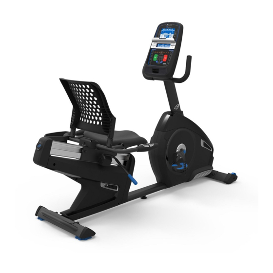
FEATURES Console Fully Shrouded Flywheel MP3 Input Pedal USB Port Storage Bin Water Bottle Holder Seat Adjustment Handle Transport Handle Handlebar, Upright Stabilizer Speakers Leveler Handlebar, Side Media Tray Contact Heart Rate (CHR) Sensors Telemetry Heart Rate (HR) Receiver Power Connector Bluetooth Connectivity (not shown) ® Transport Wheels MP3 Cord WARNING! Heart rate monitoring systems may be inaccurate. Over exercising may result in serious injury or death. -
Page 22: Console Features
Console Features The Console provides important information about your workout and lets you control the resistance levels while you exercise. The Console features the Nautilus Dual Track™ display with touch control buttons to navigate you through the exercise programs. Upper Display 100% 100% Anaerobic Anaerobic 无氧锻炼 80-90% 80-90% Aerobic Aerobic 有氧锻炼 70-80% 70-80% Fat burn Fat burn 消耗脂肪... - Page 23 Resistance Level Quick Buttons- Shifts the resistance levels to the setting quickly during a workout Achievement Indicator Lights- when an achievement level is reached or a result is reviewed, the achievement indicator light will activate Nautilus Dual Track™ Display Upper Display Data Program Display...
- Page 24 低于 Lower Display Data SPEED TIME DISTANCE DISTANCE LEVEL HEART RATE CALORIES 阻力等级 阻力等级 MPH km/h Hr MIN MILES KM The Lower Display shows the Workout Values and can be customized for each User. (Consult the “Edit User Profile” section of this manual.) CURRENT WORKOUT LAST WORKOUT 上次锻炼 本次锻炼 LONGEST WORKOUT LAST 7 DAYS Speed 最长锻炼 最近 7 天 LAST 30 DAYS CALORIE RECORD The SPEED display field shows the machine speed in miles per hour (mph) or kilometers per hour (km/h).
-
Page 25: Bluetooth ® Connectivity
Nautilus Connect™: ® Sign in to Nautilus Connect™ to instantly sync your workout data with it. Once you have an account, your Workouts will be uploaded to Nautilus Connect™ immediately after a workout through your Bluetooth device. -
Page 26: Remote Heart Rate Monitor
” option. ® Note: Nautilus Connect™ will automatically sync your workouts with MyFitnessPal after the initial syncing. ® A User’s Guide for Nautilus Connect™ can be found online at www.nautilusconnect.com. Remote Heart Rate Monitor Monitoring your Heart Rate is one of the best procedures to control the intensity of your exercise. Contact Heart Rate (CHR) sensors are installed to send your heart rate signals to the Console. The Console can also read telemetry HR signals from a Heart Rate Chest Strap Transmitter that operates in the 4.5kHz - 5.5kHz range. Note: The heart rate chest strap must be an uncoded heart rate strap from Polar Electro or an uncoded POLAR compatible model. - Page 27 The Heart Rate table is an estimate of what Heart Rate Zone (HRZ) is effective to burn fat and improve your cardiovas- cular system. Physical conditions vary, therefore your individual HRZ could be several beats higher or lower than what is shown. The most efficient procedure to burn fat during exercise is to start at a slow pace and gradually increase your intensity until your heart rate reaches between 60 – 85% of your maximum heart rate. Continue at that pace, keeping your heart rate in that target zone for over 20 minutes. The longer you maintain your target heart rate, the more fat your body will burn.
-
Page 28: Operations
OPERATIONS What to Wear Wear rubber-soled athletic shoes. You will need the appropriate clothes for exercise that allow you to move freely. How Often Should You Exercise Consult a physician before you start an exercise program. Stop exercising if you feel pain or tightness in your chest, become short of breath, or feel faint. Contact your doctor before you use the machine again. Use the values calcu- lated or measured by the machine’s computer for reference purposes only. The heart rate displayed on the console is an approximation and should be used for reference only. -
Page 29: Initial Setup
Initial Setup During the first power-up, the Console should be setup with the date, time and your preferred measurement units. 1. D ate: Push the Increase/Decrease buttons to adjust the currently active value (flashing). Push the Left/Right buttons to change which segment is the currently active value (month / day / year). Push OK to set. 3. T ime: Push the Increase/Decrease buttons to adjust the currently active value (flashing). Push the Left/Right buttons to change which segment is the currently active value (hour / minute / AM or PM). Push OK to set. 5. U nits of Measurement: Push the Increase/Decrease buttons to adjust between “MILES” (Imperial English) or “KM” (metric). Push OK to set. The Console goes back to the Power-Up / Idle Mode screen. Note: To adjust these selections, consult the “Console Set-Up Mode”... - Page 30 User Profiles are assigned the default values until they are customized by editing. Be sure to edit the User Profile for more accurate calorie and heart rate information. From the Power-Up Mode screen, push the User button to select one of the User Profiles. The Console will display the name of the User Profile and the User Profile Icon. Edit User Profile 1. From the Power-Up Mode screen, push the User button to select one of the User Profiles. 2. Push the OK button to select it. 3. T he Console display shows the EDIT prompt and the current User Profile name. Push OK to start the Edit User Profile option. T o exit the Edit User Profile option, push the PAUSE/END button and the console will go back to the Power-Up Mode screen. 4.
-
Page 31: Profile Programs
9. The Console will go to the Power-Up Mode screen with the user selected. Reset a User Profile 1. From the Power-Up Mode screen, push the User button to select one of the User Profiles. 2. Push the OK button to select it. 3. T he Console display shows the current User Profile name and the EDIT prompt. Push the Increase() or Decrease() buttons to change the prompt. - Page 32 Easy Tour Easy Tour Stream Crossing Stream Crossing Pike’s Peak Pike’s Peak Mount Hood Mount Hood Pyramids Pyramids Summit Pass Pyramids Summit Pass Pyramids Pyramids Summit Pass Summit Pass Pyramids Pyramids Summit Pass Summit Pass CHALLENGES Uphill Finish Cross-Training Uphill Finish Uphill Finish Cross-Training Cross-Training...
- Page 33 until your heart rate reaches the “Test Zone”. This zone is individually computed to be near 75 percent of the maximum heart rate of your User Profile. When you reach the Test Zone, the machine holds the intensity steady for 3 minutes. This lets you reach a stable condition (where your heart rate becomes steady). At the end of the 3 minutes, the Console measures your heart rate and the power output. These numbers, along with information about your age and weight, are computed to produce a “Fitness Score”. Note: Fitness Test scores should only be compared to your previous scores and not to other User Profiles. Compare your Fitness Scores to see your improvement.
-
Page 34: Pausing Or Stopping
3. Push the Increase() or Decrease() buttons to select the Goal type, and push OK. 4. Push the Increase() or Decrease() buttons to set the goal value for the workout. Note: Be sure to allow time for your heart rate to reach the desired heart rate zone when setting the goal. 5. P ush OK to start the workout. A User can set a Heart Rate zone instead of a value by selecting the Heart Rate Control - User program. The Console will adjust the workout to keep the User in the desired Heart Rate zone. -
Page 35: Results / Cool Down Mode
Down resistance level can be adjusted with the Resistance Increase and Decrease buttons, but the Console will not dis- play the value. You can push PAUSE/END to stop the Results / Cool Down period and go back to Power-Up Mode. If there is no RPM or HR signal, the Console automatically goes into Sleep Mode. GOAL TRACK Statistics (and Achievements) The statistics from every workout are recorded to a User Profile. The Nautilus Dual Track™ Console shows the Goal Track workout Statistics on the Lower Display in three channels: a.) T IME (total), DISTANCE (total), and CALORIES (total) b.) S PEED (average), RPM (average), and HEART RATE (average) c.) T IME (average), DISTANCE (average) / or LEVEL (average) *, and CALORIES (average) * If the Goal Track Statistic is a single workout, LEVEL (average) is displayed. If the Goal Track Statistic is a... - Page 36 The BMI Measurement is a useful tool that shows the relationship between weight and height that is associated with body fat and health risk. The table below gives a general rating for the BMI score: Underweight Below 18.5 Normal 18.5 – 24.9 Overweight 25.0 – 29.9 Obesity 30.0 and above...
-
Page 37: Console Service Mode
CONSOLE SETUP MODE The Console Setup Mode lets you input the date and time, set the units of measurement to either English or Metric, control the sound settings ( on/ off), or see maintenance statistics (Error Log and Run Hours – for service technician use only). 1. H old down the PAUSE/END button and Right button together for 3 seconds while in the Power-Up Mode to go into the Console Setup Mode. Note: Push PAUSE/END to exit the Console Setup Mode and return to the Power-Up Mode screen. The Console display shows the Date prompt with the current setting. To change, push the Increase/Decrease buttons to adjust the currently active value (flashing). Push the Left/Right buttons to change which segment is the currently active value (month / day / year). Push OK to set. The Console display shows the Time prompt with the current setting. Push the Increase/Decrease buttons to adjust the currently active value (flashing). Push the Left/Right buttons to change which segment is the currently active value (hour / minute / AM or PM). -
Page 38: Maintenance
MAINTENANCE Read all maintenance instructions fully before you start any repair work. In some conditions, an assistant is required to do the necessary tasks. Equipment must be regularly examined for damage and repairs. The owner is responsible to make sure that regular maintenance is done. Worn or damaged components must be repaired or replaced immediately. Only manufacturer supplied components can be used to maintain and repair the equipment. -
Page 39: Maintenance Parts
Maintenance Parts Console Stabilizer, Front Contact Heart Rate Sensor (CHR) Console Mast Transport Wheel Flywheel Seat Back Pedals Drive Pulley Seat Cover Shroud, Right Servo Motor Water Bottle Holder Shroud, Upper Brake Assembly Handlebar, Side Shroud, Left Drive Belt Seat Bottom Crank Arm Speed Sensor Magnet Seat Adjustment Handle Console Cable, Lower Speed Sensor... -
Page 40: Troubleshooting
TROUBLESHOOTING Condition/Problem Things to Check Solution No display/partial display/ Check electrical (wall) Make sure unit is plugged into a functioning wall outlet. unit will not turn on outlet Check connection at front Connection should be secure and undamaged. Replace of unit adapter or connection at unit if either are damaged. Check data cable integrity All wires in cable should be intact. - Page 41 Check magnet position Magnet should be in place on pulley. (requires shroud removal) Check Speed Sensor Speed sensor should be aligned with magnet and connected to (requires shroud removal) data cable. Realign sensor if necessary. Replace if there is any damage to the sensor or the connecting wire. Console shuts off (enters Check electrical (wall) Make sure unit is plugged into a functioning wall outlet.
- Page 42 Nautilus Bowflex Schwinn Universal ® ® ® ® 8007104.040115.C...
Need help?
Do you have a question about the R686 and is the answer not in the manual?
Questions and answers
adj resistance. When I try and increase resistance it goes to max
The Nautilus R686 resistance may go to maximum when trying to adjust it due to a malfunction in the resistance adjustment system. Possible causes include a faulty Resistance Increase button, a software issue, or a problem with the resistance motor or control board. Regular maintenance and inspection for damaged components are recommended to prevent such issues.
This answer is automatically generated