Advertisement
Quick Links
Thank you for purchasing KYOWA's product
Thank you for purchasing KYOWA's product
AMA-A Small-sized Low Capacity Triaxial
sized Low Capacity Triaxial
Acceleration Transducers (hereinafter referred to as
Acceleration Transducers (hereinafter referred to as
the AMA-A). Before using the product, please read
A). Before using the product, please read
this Instruction Manual carefully. Also, keep the
this Instruction Manual carefully. Also, keep the
manual within easy reach so that you can refer to it
manual within easy reach so that you can refer to it
whenever necessary.
1. CALLING THE OPERATOR'S ATTENTION
In order to avoid instrument failure or
In order to avoid instrument failure or
malfunction, be sure to observe
malfunction, be sure to observe the
Notes
accompanying instructions.
accompanying instructions.
2. INSTALLATION
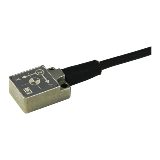
2.1 Sensitive axis
When installing the transducer, make sure of the
When installing the transducer, make sure of the
model name and install it to provide a proper
model name and install it to provide a proper
sensitive axis.
Indicates the center of element
Indicates the center of element
Figure 2-1
2.2 How to install
(1) To install, use M1.6 screw (recommended
(1) To install, use M1.6 screw (recommended
tensile strength ranking [12.9], longer than 6
tensile strength ranking [12.9], longer than 6
mm*). Drill holes in the measuring object. The
mm*). Drill holes in the measuring object. The
holes' effective screw depth should be longer
screw depth should be longer
than the mounting screws, L1≦L2. The
distance between the holes should be 7±0.1
distance between the holes should be 7±0.1
mm. (Figure 2-2)
*To install the AMA-A into the 3-axis angular rate
gyro GSAT-A, use M1.6 screw (length: 6 to 8
use M1.6 screw (length: 6 to 8 mm).
Figure 2-2
AMA-A Acceleration
cceleration Transducer INSTRUCTION MANUAL
ATTENTION
L2. The
axis angular rate
INSTRUCTION MANUAL
(2) Clean the mounting area.
(3) Also clean the mounting surface of the transducer.
(3) Also clean the mounting surface of the transducer.
(4) Apply the silicone grease lightly between the transducer
(4) Apply the silicone grease lightly between the transducer
and measuring object. The tightening torque is 0.1 to 0.12
and measuring object. The tightening torque is 0.1 to 0.12
N・m (approx. 1.0 to 1.2 kgf
Do not disassemble the transducer.
disassemble the transducer.
This transducer is extra sensitive to impact.
This transducer is extra sensitive to impact.
Avoid, therefore, dropping it or hitting against a hard
Avoid, therefore, dropping it or hitting against a hard
matter. Avoid impact in excess of its safe overload
matter. Avoid impact in excess of its safe overload
2
rating (19,613m/s
). If not, the transducer may be
). If not, the transducer may be
damaged. Take great care to handle it properly.
When installing, carefully avoid external force such
When installing, carefully avoid external force such
as bending or twisting on the transducer. It is ideal
as bending or twisting on the transducer. It is ideal
that when installed, the transducer is in complete
that when installed, the transducer is in complete
close contact with the measuring object.
close contact with the measuring object.
If the transducer is installed using an adhesive,
excessive force applied to remove it may deform the
excessive force applied to remove it may deform the
transducer's cabinet or cause failure of the
transducer's cabinet or cause failure of the
transducer. If the transducer is to be used repeatedly,
transducer. If the transducer is to be used repeatedly,
be sure to install it using screws.
be sure to install it using screws.
The grounding is an effective measures a
The grounding is an effective measures against noise
and failure of the transducer caused by electric
and failure of the transducer caused by electric
charge. (Figure 2-3)
Measuring object (conductor)
Measuring object (conductor)
The transducer's connector area is not waterproof.
The transducer's connector area is not waterproof.
Take care to avoid water and highly humid (over
Take care to avoid water and highly humid (over
85%) environment.
3. CONNECTION
3.1 Connect the transducer to the measuring instrument via
3.1 Connect the transducer to the measuring instrument via
an optional relay cable (approx.
3.2 Label colors on the connector to measuring instrument
3.2 Label colors on the connector to measuring instrument
of the relay cable indicate axes (X: Yellow, Y: Green,
of the relay cable indicate axes (X: Yellow, Y: Green,
or Z: Blue). Before connecting the transducer to the
measuring instrument, check label colors.
measuring instrument, check label colors.
Approx. 30cm
Approx. 30cm
←To relay
IM-T-279 2014.6
kgf・cm).
Notes
Notes
care to handle it properly.
alled using an adhesive,
Figure 2-3
Figure 2
approx. length: 30 cm).
connecting the transducer to the
Label
Label
To measuring instrument →
To measuring instrument
Figure 3-1
Figure 3
X
Y
Z
(blue)
Advertisement

Related Manuals for KYOWA AMA-A


Summary of Contents for KYOWA AMA-A
- Page 1 Approx. 30cm Approx. 30cm *To install the AMA-A into the 3-axis angular rate axis angular rate Label Label gyro GSAT-A, use M1.6 screw (length: 6 to 8 use M1.6 screw (length: 6 to 8 mm).
- Page 2 Sensor Check LED lights up and the Model Cable length Connector AMA-A outputs voltage at random. If the AMA-A does PRC03-12A10-7M not output voltage at random while pressing the Sensor Approx. TE-55 Check button, the AMA-A might be failure.
- Page 3 6. SPECIFICATIONS, ACCESSORIES 6.1 Specifications Model AMA-A-2 AMA-A-5 Rated capacity ±19.61m/s ±49.03m/s (±2G) (±5G) Rated output ±2.0 V ±0.2 V Nonlinearity Within ±1%RO Hysteresis Within ±1%RO Frequency DC to 500Hz (Sensitivity response range deviation: Within ±10%) Transverse 4% or less...
- Page 4 ○Dimensions [Sensor] [Relay] URL http://www.kyowa-ei.com...
Need help?
Do you have a question about the AMA-A and is the answer not in the manual?
Questions and answers