Table of Contents
Advertisement
Quick Links
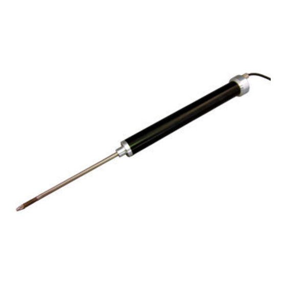
DTS-A-100 DISPLACEMENT TRANSDUCER INSTRUCTION MANUAL
Thank you for purchasing the KYOWA product. Before using it, read this
instruction manual carefully. Also, keep the manual within easy reach so that
you can refer to whenever necessary.
Specifications and dimensions described in this manual could be changed
without notice. Please visit our website for the latest version.
1. Calling the operator's attention
The following cautionary symbols and headlines are used to invite the
operator's attention. Be sure to observe the accompanying precautions in
order to safeguard the operator and preserve the performance of the
instrument.
Improper handling can cause serious injury to the
Warning
operator.
Cautions are given to invite the operator's attention, in
Caution
order to avoid instrument failure or mal-function.
2. Important notice
Unless specified, the transducer must not be used under hydrogen
environment.
3. Safety Precautions
As you push the rod inward, the rod returns to its initial position by
●
reaction force. Handle the product with care to avoid eye poking.
4. Handling Precautions
Caution
Do not apply excessive axial or bending force on the rod.
●
Do not rotate the rod. (For replacing accessories, see 9.)
●
Do not disassemble the product.
●
Do not use the product under water and dusty environment.
●
Use the product under environment without vibration.
●
Pay similar attentions toward the product as one gives to regular dial
●
gages.
Always keep the rod clean.
●
Make sure that the bending radius of cable is longer than 10 times of a
●
diameter of the cable.
5. Installation
5.1 Fix the DTS-A to the fixed point by using the accessory 2 mounting
bands (FXBP-100A), 2 wing bolts (M4×12) and M6 bolt.
The M6 bolt is not included.
5.2 Make sure the displacement of 0.5 mm or more is applied to the DTS-A.
5.3 The DTS-A and dial gage measures data by contacting the probe onto
the measuring point. However, some DTS-A rods may not track dynamic
data correctly. Make sure the rods works correctly.
5.4 To fix the rod to the measuring point, remove the prove and fix the rod to
the measuring point by using a screw (M2.5).
Warning
5.5 To measure displacement by pulling the rod, connect the accessory
adapter into the rod end.
6. Connection
6.1 Connect the DTS-A to a measuring instrument.
6.2 Connect the connector plug as follows.
Connector plug
6.3 After the power ON, always preheat the product for approximately 5 to 10
minutes.
7. Conversion
7.1 Use the calibration constant described on the Test Data Sheet to convert
a measured value into a displacement value.
7.2 When a strain amplifier is in use, output reads in ×10
Find a displacement value corresponding to ×10
displacement value through multiplication using the following equation.
Displacement (mm) =Strain amplifier's output (×10
x Calibration constant (mm/1×10
7.3 When using an amplifier of other type or a recorder, first find the exact
bridge exciting voltage applied. Second, find the displacement value that
corresponds to 1(μV) output voltage against 1(V) bridge excitation voltage.
Then, obtain the displacement value through multiplication using the
following equation.
Displacement (mm) =
Bridge output voltage (μV)
Bridge excitation voltage (V)
Sensitivity Decrease due to Cable Extension
If a strain-gage transducer is connected to a signal conditioner, digital
indicator or strain amplifier via extension cable, we will not ignore the
sensitivity decrease due to the extension cable resistance which lowers
the voltage applied to the transducer.
The rated output with lowered sensitivity is obtained from the following
equation:
Rated output :ε
=(
0
R:Transducer's input resistance (Ω)
r:Extension cable's reciprocating resistance (Ω/m)
L:Extension cable length (m)
ε
:Rated output written in the Test data sheet
i
IM-T-287C Jun. 2021
Adapter
DTS-A
(Shield is not connected to the chassis.)
-6
equivalent strain.
strain. Then, obtain a
-6
-6
strain)
-6
strain)
×Calibration constant (mm/1μV/V)
R
)ε
i
R+(r × L)
Advertisement
Table of Contents

Subscribe to Our Youtube Channel
Related Manuals for KYOWA DTS-A-100


Summary of Contents for KYOWA DTS-A-100
- Page 1 IM-T-287C Jun. 2021 DTS-A-100 DISPLACEMENT TRANSDUCER INSTRUCTION MANUAL Thank you for purchasing the KYOWA product. Before using it, read this 5.5 To measure displacement by pulling the rod, connect the accessory instruction manual carefully. Also, keep the manual within easy reach so that adapter into the rod end.
- Page 2 Do not apply excessive axial or If abnormal resistance is found, the DTS-A may be failure. bending force on the rod. Or, the product may be damaged. Contact KYOWA or our representatives. Pin (φ2×20) Caution To measure insulation resistance, apply a voltage lower than 50V to the ●...
- Page 3 Roller-equipped probe: SH-2-DT Extension rod...
- Page 4 Measuring Force Approx. 5 N Weight Approx.110g (Excluding Cable) Degree of protection IP40 (IEC 60529) Compliance Directive 2011/65/EU, (EU) 2015/863 (10 restricted substances) (RoHS) [NOTE] Products with CE Marking are compliant European RoHS Directive. Website : www.kyowa-ei.com...
Need help?
Do you have a question about the DTS-A-100 and is the answer not in the manual?
Questions and answers