Table of Contents
Advertisement
Quick Links
2004-2-4
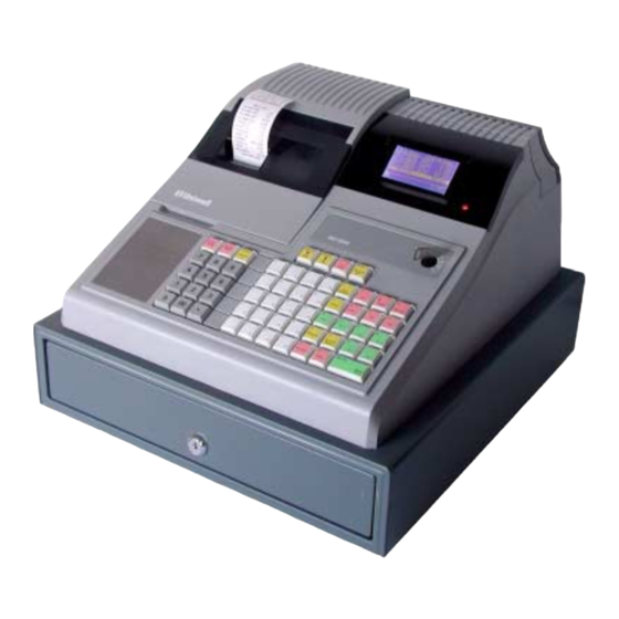
LX-5000
series 02 type
LX-5600 2-sheet dot matrix printer
LX-5700 2-sheet thermal printer
LX-5750 1-sheet thermal printer
Interfaces & /
Peripherals /
Manual
/"
CAUTION!
When the control key position is LOCK, the display is
off and keyboard is disabled but the ECR's power is still
ON. So that before you connect the cable of
peripherals, make sure that the AC cord is disconnected
otherwise the ECR will be damaged.
Advertisement
Table of Contents

Subscribe to Our Youtube Channel
Related Manuals for Uniwell LX-5000 Series


Summary of Contents for Uniwell LX-5000 Series
- Page 1 2004-2-4 LX-5000 series 02 type LX-5600 2-sheet dot matrix printer LX-5700 2-sheet thermal printer LX-5750 1-sheet thermal printer Interfaces & / Peripherals / Manual /" CAUTION! When the control key position is LOCK, the display is off and keyboard is disabled but the ECR's power is still ON.
-
Page 2: Table Of Contents
CONTENTS I. INTERFACE INFORMATION ..................1 II. IRC SYSTEM ........................4 III. PERIPHERALS......................... 6 1. TERMINAL PRINTERS......................6 1) TP-822/832 (Kitchen Printer, connected to ch-A)............... 6 2) TP-620 (Slip Printer, connected to ch-A)..................7 3) CBM-1000 (Thermal Kitchen Printer, connected to ch-A via NA-710/730) ......8 4) TM-T88III (Thermal Slip Printer, connected to ch-B).............. -
Page 3: Interface Information
I. INTERFACE INFORMATION The following interfaces are provided: Channel Used for IRC : up to 8 units including an ECR master or PC as IRC master (Tensai2000) via NA-720 4 kitchen printer -- one of kitchen printer can be used as a slip printer TP-822 : Citizen DP-416 impact dot matrix printer with auto cutter TP-832 : Citizen LT-1320 thermal printer with auto cutter A RS485... - Page 4 System Configuration Maximum 8 units can be connected via IRC line including the master, max. 4 kitchen printers and max. 4 slip printers. However, an ECR can use one slip printer. PC as IRC master (Tensai2000) Slip printer, max. 4 RS232C TP-620 NA-720...
- Page 5 Pin Assignment & Character Structures CHANNEL A PIN # SIGNAL FUNCTION (RS485, RJ-45 modular type connector) DATA+ Comm. data signal (+) Baud rate : 19200 bps or 38400 bps [SF-89.a] DATA- Comm. data signal (-) CTL+ Comm. line control (+) Character structure : start bit = 1 bit N.C.
-
Page 6: Irc System
II. IRC SYSTEM The master PC or ECR can transmit programming data to the slave ECRs and collect the sales data from the slave ECRs via channel A. PC as Master using PC-IRC communication module Tensai2000 ECR as Master : Any ECR can be a master ECR. Preparation Before using the IRC system, the following presetting must be performed: a) For new machines being added to the system, perform RAM test SP-9901 to erase all RAM... - Page 7 c) IRC status check operation Either a PC as master or ECR as master, perform SP/X-8800 IRC STATUS CHECK on ECR as follows: < SP >--(8800)--[X2/ENTER]--[ • /ENTER] or select IRC PROGRAM and 8800 IRC STATUS CHECK from the list <...
-
Page 8: Peripherals
III. PERIPHERALS 1. TERMINAL PRINTERS Refer to VII. Cable Connection (page 22). Following printers are available. Model Used for Connected to TP-822/832 kitchen printer (dot/thermal) channel A CBM-1000 kitchen printer (thermal) channel A via NA-710/730 TP-620 slip printer channel A TM-T88III slip printer (thermal) channel B... -
Page 9: Tp-620 (Slip Printer, Connected To Ch-A)
2) TP-620 (Slip Printer, connected to ch-A) form stopper release switch Cancels the form stopper. two-digit LED RELEASE switch Releases paper or starts / stops test printing. PRINT switch Feeds paper if buffer is empty or prints data which is in buffer. FUNCTION switch power switch Back feeds paper. -
Page 10: Cbm-1000 (Thermal Kitchen Printer, Connected To Ch-A Via Na-710/730)
3) CBM-1000 (Thermal Kitchen Printer, connected to ch-A via NA-710/730) Before using, ECR original character must be installed by using CBM-1000-UW ROM. ECR SETTINGS --- same settings as TP-822/832 (page 6) NETWORK ADAPTER SETTINGS NA-710 : 1 printer can be connected NA-730 : up to 3 printers can be connected Unplug the cord and set the dip switches as shown below: Plug the cord to fix the setting. -
Page 11: Tm-T88Iii (Thermal Slip Printer, Connected To Ch-B)
4) TM-T88III (Thermal Slip Printer, connected to ch-B) Before using, ECR original character must be installed standard by using TM-T88III-UW(s) ROM. Communication setting of ECR for TM-T88III has been fixed to: 19200 bps, even parity, 8-bit data, 2 stop bits. ECR SETTINGS a) Select following: [SF-83.h]... -
Page 12: Scanner
2. SCANNER The handy scanner models HC66R (BHS-6060/R) and BCH5442-STA which are supplied by your destributor can be used immediately after the scanner cable is connected to channel B, D or E. Refer to VII. Cable Connection (page 25). If they are supplied from third party or a scanner of other manufacturers, some settings are required. Refer to the next page. - Page 13 Settings for scanner from third party When you are using BHS-6060 and BCH-5442-STA supplied from third party or a scanner of other manufacturers, some settings are required. Perform the following steps: 1. Connect the scanner to the correct ECR's interface port. RTS signal need to be wired. Refer to VII.
-
Page 14: Scale
3. SCALE A scale which has RS232C interface can be connected through either one of channel B, D or E. Refer to VII. Cable Connection (page 24). Recommended models: DIGI DS-640, NCI 6720, BARKEL CX-9/CX-10, AVERY A702 Select the scale which matches the scale information described in the following pages. ECR SETTING a) Set the following flags: SP-100 System Function Flag... -
Page 15: Scale Information Of Icl Protocol [Sf-25.A=0]
1) Scale Information of ICL Protocol [SF-25.a=0] DATA FORMAT (ICL PROTOCOL) The format of the data string from the scale is: These bytes are defined as follows: < ID > ID is an identification byte defining maximum capacity and minimum increments of the scale. Typical capacities and increments are listed below with allocated codes. - Page 16 ICL PROTOCOL SCALE Communication starts immediately after SCALE key is pressed. inquires about scale condition receive data error NULL weight data valid ready to send weight has been changed requests weight data receive data error transmits weight data receive data error re-transmits weight data receive data error data match...
-
Page 17: Scale Information Of W Protocol [Sf-25.A=1]
2) Scale Information of W Protocol [SF-25.a=1] DATA FORMAT (W PROTOCOL) The format of the data string from the scale is: Weight data recognized by ECR kg [SF-25.e=1] XX.XXX kg lb [SF-25.e=0] XX.XX lb (W5 = NUL) W PROTOCOL SCALE Communication starts immediately after SCALE key is pressed. -
Page 18: Eft Terminals
4. EFT TERMINALS One of EFT terminals "G&D, Celectronic, Krone and C-ZAM" can be connected to channel B. C-ZAM EFT terminal only for Chip Card has been corresponded. Refer to VII. Cable Connection (page 27). Credit Card EFT Card Chip Card ch-B (RS232C) to Host Terminal... -
Page 19: Pc Communication
IV. PC COMMUNICATION The following functions can be done with a PC through either one of channel B, D or E. Refer to VII. Cable Connection (page 24). 1. BATCH COMMUNICATION Set terminal address (PGM-172) to communicate with ECR. Refer to the programming manual for the sequence. -
Page 20: Esf Data Transfer (Electronic Store & Forward)
3. ESF DATA TRANSFER (Electronic Store & Forward) All registrations performed in the R position only are recorded in ESF memory on the optional RAM board. Select "ESF function available" [SF-78.a=1] to use ESF memory. Attention! When the RAM board to be used for ESF is first installed, the Z-79 report must be taken to clear in the Z1/P position on ECR. - Page 21 MEDIA 6030 Direct Closing Media 6031 Tendering Amount Entered Media 6032 P/O Media media number (*) / amount 6033 R/A Media 6034 Tip Media 6036 Change Media 6037 Cheque-Cashing/Currency Exchange media number (*) / tendering amount / cashing rate / amount 6038 Media &...
-
Page 22: Ecr To Ecr Ram Data Transfer
V. ECR TO ECR RAM DATA TRANSFER ECR to ECR RAM data transfer is done by using channel B. This transfer will send the programming data and sales data. If only the programming data is required, reset the sales data by issuing all Z-reports, then follow the sequence below. PREPARATION 1) Set the baud rate by the system function flags for both ECRs. -
Page 23: Journal Data Transfer
VI. JOURNAL DATA TRANSFER The journal data is transmitted to a peripheral device through either one of channel B, D or E. Refer to VII. Cable Connection (page 26). PREPARATION Set the following flags on ECR and the peripheral device to match ECR's communication condition below: SF-90 SF-92 With journal data transfer... -
Page 24: Cable Connection
VII. CABLE CONNECTION 1. CHANNEL A --- IRC LINE RJ-45 Modular Type Cable Information Please use the straight LAN cable (shielded type) which is generally sold. RS422/485 Shielded Twisted Pair Conductor: AGW24 Characteristic impedance: < 100 ohms Capacitance per meter: 40 - 100 pF Attenuation at 1Mhz / 100m: 2 - 6 db... - Page 25 Cable connection between NA-720 (CH1) and PC To NA-720 CH 1 To PC (RS232C) P.GND * Connect ground to D-sub shell 9-way male 9-way female D-sub connector D-sub connector Cable connection between NA-710/730 and thermal printer(s) CBM-1000 To NA-710 CH 1 To CBM-1000 To NA-730 CH 1~3 (RS232C)
-
Page 26: Channels B, D & E
2. CHANNELS B, D & E 1) ECR (ch-B) to Thermal Slip Printer TM-T88III To ECR To TM-T88III P.GND F.G. 9-way male 25-way male D-sub connector D-sub connector 2) ECR (ch-B, ch-D/E) to Scale To ECR To Scale (ch-B, ch-D/E) P.GND 9-way male 25-way male... -
Page 27: Ecr (Ch-B, Ch-D/E) To Handy Scanner
4) ECR (ch-B, ch-D/E) to Handy Scanner Handy Scanner Connector P.GND P.GND HANDY SCANNER +5V * 9-way female 9-way male D-sub connector D-sub connector *max. 200 mA 5) ECR (ch-B, ch-D/E) to Flat Bed Scanner To ECR To Flat Bed Scanner P.GND 9-way male... -
Page 28: Ecr (Ch-B, Ch-D/E) To Peripheral For Journal Data Transfer
6) ECR (ch-B, ch-D/E) to Peripheral for Journal Data Transfer To ECR To Peripheral P.GND RTS or DTR 9-way male 9-way female D-sub connector D-sub connector 7) ECR (ch-B) to ECR (ch-B) for RAM Data Transfer To ECR To ECR P.GND P.GND 9-way male... -
Page 29: Ecr (Ch-B) To Eft Terminal
8) ECR (ch-B) to EFT Terminal To ECR To Celectronic EFT Terminal P.GND 9-way male 9-way male D-sub connector D-sub connector To ECR To G&D/Krone EFT Terminal P.GND 9-way male 9-way male D-sub connector D-sub connector To ECR To C-ZAM EFT terminal P.GND 9-way male...
Need help?
Do you have a question about the LX-5000 Series and is the answer not in the manual?
Questions and answers