Table of Contents
Advertisement
Quick Links
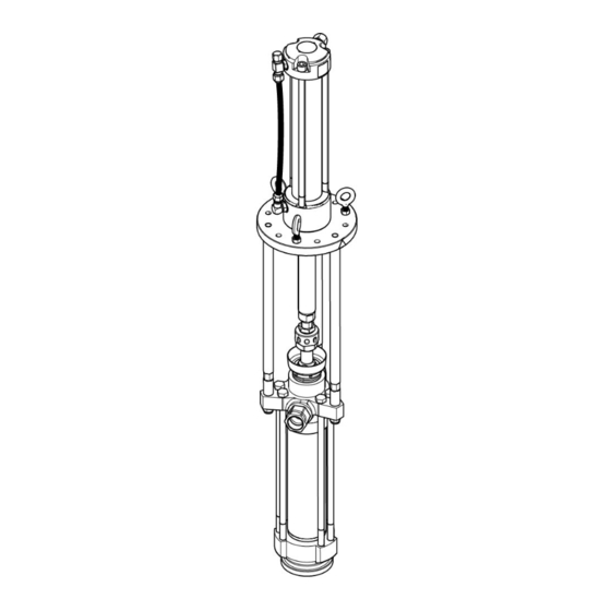
Operation and Parts
RoadLazer HPS 135 and HPS 180
Hydraulic Pumping Systems
Pump System for use with traffic paints. For professional use only. Not approved for use in
explosive atmospheres or hazardous (classified) locations.
See page 2 for model information.
Maximum Fluid Working Pressure:
1000cc Pumps: 2500 psi (17 MPa, 172 bar)
1400cc Pumps: 2000 psi (14 MPa, 138 bar)
Important Safety Instructions
Read all warnings and instructions in this manual
before using the equipment. Be familiar with the
proper control and usage of the equipment.
Save these instructions.
3A9247A
ti42045a
EN
Advertisement
Table of Contents

Subscribe to Our Youtube Channel
Related Manuals for Graco RoadLazer HPS 135 Severe Duty


Summary of Contents for Graco RoadLazer HPS 135 Severe Duty
- Page 1 Operation and Parts RoadLazer HPS 135 and HPS 180 Hydraulic Pumping Systems 3A9247A Pump System for use with traffic paints. For professional use only. Not approved for use in explosive atmospheres or hazardous (classified) locations. See page 2 for model information. Maximum Fluid Working Pressure: 1000cc Pumps: 2500 psi (17 MPa, 172 bar) 1400cc Pumps: 2000 psi (14 MPa, 138 bar)
-
Page 2: Table Of Contents
Storage Maintenance ..... . 8 Graco Standard Warranty....16 Lifetime Service Maintenance . -
Page 3: Warnings
Warnings Warnings The following warnings are for the setup, use, grounding, maintenance, and repair of this equipment. The exclamation point symbol alerts you to a general warning and the hazard symbols refer to procedure-specific risks. When these symbols appear in the body of this manual or on warning labels, refer back to these Warnings. Product-specific hazard symbols and warnings not covered in this section may appear throughout the body of this manual where applicable. - Page 4 Warnings WARNING EQUIPMENT MISUSE HAZARD Misuse can cause death or serious injury. • Do not operate the unit when fatigued or under the influence of drugs or alcohol. • Do not exceed the maximum working pressure or temperature rating of the lowest rated system component.
-
Page 5: Component Identification
Component Identification Component Identification Ref. Description Ref. Description Tie Rod with Extension Hydraulic Inlet Hex Nuts Hydraulic Outlet Packing Nut/Wet Cup Motor, HPS Packing Nut Wrench Displacement Pump, Dura-Flo Plug Coupling Adapter Cup Cover Coupling Nut Coupling Collars 3A9247A... -
Page 6: Pump Assembly
Pump Assembly Pump Assembly NOTICE Use the 3 lift rings (eyebolts), attached to the mounting plate, for lifting and moving the motor into place for installation. Moving the motor by any other means could damage the pump assembly. 1. Assemble Coupling Adapter (H) to the Motor (F). 2. -
Page 7: Pressure Relief Procedure
Pressure Relief Procedure Pressure Relief Procedure This equipment stays pressurized until pressure is manually relieved. To help prevent serious injury from pressurized fluid, such as skin injection, splashing fluid and moving parts, follow the Pressure Relief Procedure when you stop spraying and before cleaning, checking, or servicing the equipment. -
Page 8: Maintenance
2. Stop the pump at the bottom of its stroke. 3. Perform the Pressure Relief Procedure, page 7. 1. Fill the Packing Nut/Wet Cup (P) 1/3 full with Graco Throat Seal Liquid (TSL). 4. Disconnect the hydraulic hose. Plug all hydraulic hoses immediately to prevent the contamination of 2. -
Page 9: Recycling And Disposal
Recycling and Disposal Recycling and Disposal End of Product Life End of Life Disposal At the end of the product’s useful life, dismantle and If the pumping system is in a condition that it can no recycle it in a responsible manner. longer operate, the pump should be taken out of service and dismantled. -
Page 10: Hydraulic Motor Parts
Hydraulic Motor Parts Hydraulic Motor Parts † Included in Repair Kit 288061 ★ Included in Repair Kit 25V515 ‡ Included in Repair Kit 287870 3A9247A... -
Page 11: Hydraulic Motor Parts List
26D808 ROD, tie 120065 FITTING, hydraulic 101712 NUT, lock 26D972 HOSE, hydraulic 26D761 BOLT, socket head cap, tie rod 15G878 LABEL, graco logo 184096 NUT, coupling 40▲ 15H108 LABEL, warning, pinch PUMP, Dura-Flo 120112 FITTING, cap, nut 25V502 1000cc Lower, Severe Duty... -
Page 12: Dimensions And Mounting Hole Layouts
Dimensions and Mounting Hole Layouts Dimensions and Mounting Hole Layouts 3A9247A... -
Page 13: Technical Specifications
Technical Specifications Technical Specifications Hydraulic Motor U.S. Metric Hydraulic Inlet Pressure Range 50-3000 psi 0.3-20.7 MPa, 3.4-206.8bar Hydraulic Flow required at 45 cpm 10 gpm 38 lpm Stroke Length 11.25 in. 286 mm Hydraulic Motor Size 55 cu in. 900 cc Hydraulic Inlet JIC - 8 Hydraulic Outlet... - Page 14 Technical Specifications Dura-Flo XL 1000cc Pumps Models 25U989, 26D813 U.S. Metric Ratio 0.9:1 Maximum Fluid Working Pressure 2500 psi 17 MPa, 172 bar Maximum Hydraulic Inlet Pressure 3000 psi 21 MPa, 207bar Displacement Per Cycle 0.264 gallons 1000cc Maximum Speed 45 cpm Maximum Pump Operating Temperature 100°...
- Page 15 Technical Specifications Dura-Flo XL 1400cc Pumps Models 26D809, 26D814 U.S. Metric Ratio 0.7:1 Maximum Fluid Working Pressure 2000 psi 14 MPa, 138 bar Maximum Hydraulic Inlet Pressure 3000 psi 21 MPa, 207 bar Displacement Per Cycle 0.370 gallons 1400cc Maximum Speed 45 cpm Maximum Pump Operating Temperature 100°...
-
Page 16: Graco Standard Warranty
With the exception of any special, extended, or limited warranty published by Graco, Graco will, for a period of twelve months from the date of sale, repair or replace any part of the equipment determined by Graco to be defective.
Need help?
Do you have a question about the RoadLazer HPS 135 Severe Duty and is the answer not in the manual?
Questions and answers