Table of Contents
Advertisement
Quick Links
Instructions - Parts List
ACETAL AND POLYPROPYLENE
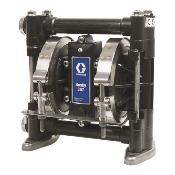
Husky
Diaphragm Pumps
For pumping transfer applications. For professional use only.
Only pumps with acetal fluid sections are approved for use in European explosive
atmosphere locations.
100 psi (0.7 MPa, 7 bar) Maximum Fluid Working Pressure
100 psi (0.7 MPa, 7 bar) Maximum Air Input Pressure
*Model No. D31 ___ Acetal Pumps**, Series F
*Model No. D32 ___ Polypropylene Pumps, Series F
*Model No. D3A ___ Acetal BSPT Pumps**, Series F
*Model No. D3B ___ Polypropylene BSPT Pumps, Series F
* To determine the Model No. for your pump and for additional models, refer to the Pump Matrix on page 26.
** Pumps with Acetal fluid sections are certified:
II 2 GD
Ex h IIC 66°...135°C Gb
Ex h IIIC T135°C Db
ATEX T-code rating is dependent on the temperature
of the fluid being pumped. Fluid temperature is limited
by the materials of the pump interior wetted parts.
See Technical Data for the maximum fluid operating
temperature for your specific pump model.
Important Safety Instructions
Read all warnings and instructions in this
manual. Save these instructions.
Tel: 866-777-6060
Fax: 866-777-6383
307 Air-Operated
Springer Pumps, LLC
308553ZAE
Website: www.springerpumps.com
Int'l: +001 267 404 2910
EN
01428B
Advertisement
Table of Contents


Need help?
Do you have a question about the Husky 307 F Series and is the answer not in the manual?
Questions and answers