Hyco Accona Product Instruction Manual
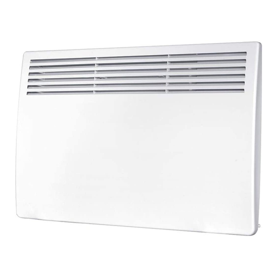
Panel heater
Hide thumbs
Also See for Accona:
- Product instruction manual (17 pages) ,
- Product instruction manual (17 pages)

Related Manuals for Hyco Accona


Summary of Contents for Hyco Accona
- Page 1 Product Instruction Manual Accona AC500T, AC1000T, AC1500T, AC2000T, AC24000T Panel Heater v24.1.4...
-
Page 2: Important Safety Points
Overview Thank you for purchasing an Accona Panel Heater. A fixed heating solution, available in 0.5, 1.0, 1.5, 2.0 and 2.4 kW models. These are suitable for application in both home and office environments. Please read and follow these instructions to ensure that installation and operation are as simple and safe as possible. - Page 3 The appliance must be permanently connected to the electrical supply through an appropriately rated isolating switch with a contact separation in all poles. This appliance must be earthed. Only connect the appliance to an electrical supply that meets the specification detailed on the rating label.
-
Page 4: Installation
1. Installation Select a location for the appliance ensuring the mounting surface is suitable for the weight and heat of the appliance. This appliance is not designed for outdoor use or use in very damp environments. If the appliance is located in a bathroom, it must be installed so that switches and other controls cannot be touched by a person in the bath or shower. - Page 5 • Mark the two ‘L’ holes as shown in diagram 2. The distance between the centres of the holes are model dependent, consult the table for the specific model being fitted. Model AC500T AC1000T AC1500T AC2000T AC2400T ‘L’ value 155 mm 155 mm 250 mm 250 mm...
- Page 6 Start position End position Diagram 4 • Fit the final fixing bracket via the air inlet grilles located on the underside of the appliance (see diagram 5). • Slide the fixing bracket along the air inlet grille until it contacts flush to wall. Mark the hole requirement on the wall and then remove the appliance by reversing the movement in the earlier step.
-
Page 7: Electrical Connection
2. Electrical Connection If the supply cord is damaged, it must be replaced by the manufacturer, its service agent or similarly qualified persons in order to avoid a hazard. The appliance must be permanently connected to the electrical supply through an appropriately rated isolating switch with a contact separation in all poles. - Page 8 3. Controls LCD Display Number Description Number Description On/ off Run on timer mode Full / half power mode Element on indicator Down Half power Manual/ auto mode select Full power Time (HH:MM) Open window detection Target temperature* Manual mode active Set select Automatic mode active Ok select...
-
Page 9: Setting The Time And Date
4. Preparing the Appliance Switching the Appliance On • Switch the power supply to the appliance on. • Turn the appliance on using the rocker switch on the right hand side of the appliance. A blue light will be illuminated above to the on/ off button. •... -
Page 10: Selecting The Operating Mode
Selecting the Operating Mode • On first power on the appliance will default to manual mode, M will be illuminated. • To select your chosen operating mode press to choose either M (manual) or A (automatic). Setting the Target Temperature •... -
Page 11: Automatic Timer Mode
Automatic Timer Mode • When programming automatic timer mode you are only setting the time periods during which you want the appliance to be switched on. • Automatic timer mode allows the appliance to be operated by a user defined schedule. - Page 12 • When programming automatic timer mode there are no minutes. It is HOUR ON/ HOUR OFF using 24-hour time format (see diagram 4). • Press SET, the day of the week will flash. • Use the arrows to select the day and press SET to confirm. The display in diagram 5 is setting the 1st segment for Monday.
-
Page 13: Child Lock
Selecting Between Full and Half Power • Press the button to choose between the settings. The current setting will be displayed by either the LO or HI icon on the display (see section 3. Controls). Child Lock • Press the arrows simultaneously and hold until the appliance beeps. -
Page 14: Cleaning And Maintenance
6. Cleaning and Maintenance This appliance should only be installed and maintained by a competent person in accordance with any local electrical regulations. Ensure any future maintenance or modifications to the appliance complies with the guidelines in these instructions. Isolate the appliance from the electrical supply before performing any maintenance task. -
Page 15: Troubleshooting
Type of heat output Electronic room temperature control plus week timer Other control option Room temperature control, with open window detection Contact details Hyco Manufacturing Ltd - 01924 225 200 8. Troubleshooting Error code Meaning Temperature sensor error - contact Hyco. -
Page 16: Guarantee And Service Policy
In order to underline the duty to dispose of this equipment separately, the product is marked with a crossed out dustbin. Hyco Manufacturing Ltd Normandy Court Castleford...
Need help?
Do you have a question about the Accona and is the answer not in the manual?
Questions and answers