Advertisement
Quick Links
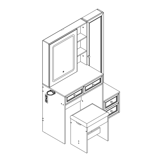
JY9942BS01
As this item contains many parts, please read the installation
instruction carefully before installation . Please use tools
properly and carefully. If you have any questions about the
product and installation, please contact us.
service@vabchesofficial.com
Our professional after-sales team will serve you online all
day.
1-49
Advertisement

Related Manuals for VABCHES JY9942BS01


Summary of Contents for VABCHES JY9942BS01
- Page 1 JY9942BS01 As this item contains many parts, please read the installation instruction carefully before installation . Please use tools properly and carefully. If you have any questions about the product and installation, please contact us. service@vabchesofficial.com Our professional after-sales team will serve you online all day.
-
Page 2: Before You Start
Before You Start Read through each step carefully and follow the proper order Separate and count all your parts and hardware Give yourself enough room for the assembly process Have the following tools: Flat Head Screwdriver, #2 Phillips Head Screwdriver and Hammer Caution: If using a power drill or power screwdriver for screwing, please be aware of to slow down and stop when screw is tight. -
Page 3: Board Identification
Board Identification Not actual size LEFT SIDE PANEL RIGHT SIDE PANEL Qty:1 Qty:1 Qty:1 PARTITION BACK SLAT FRONT SLAT Qty:1 Qty:1 Qty:1 REAR LOWER PANEL UPPER LEFT PANEL UPPER MIDDLE PANEL Qty:1 Qty:1 Qty:1 3-49... - Page 4 Board Identification Not actual size FRONT BAFFLE UPPER TOP PLATE UPPER RIGHT PANEL Qty:1 Qty:1 Qty:1 FRONT BAFFLE FIXED SHELF FIXED SHELF Qty:1 Qty:1 Qty:2 COSMETIC MIRROR UPPER BACK PANEL FIXED SHELF Qty:1 Qty:1 Qty:2 4-49...
-
Page 5: Drawer Bottom
Board Identification Not actual size UPPER BACK PANEL RIGHT DRAWER FRONT LEFT DRAWER FRONT Qty:1 Qty:1 Qty:1 DRAWER BACK PANEL DRAWER RIGHT SIDE DRAWER LEFT SIDE Qty:2 Qty:2 Qty:2 CABINET LEFT SIDE PANEL DRAWER BOTTOM CABINET TOP Qty:1 Qty:1 Qty:2 5-49... - Page 6 Board Identification Not actual size CABINET LEFT SIDE PANEL BACK SLAT FRONT SLAT Qty:1 Qty:1 Qty:1 DRAWER RIGHT SIDE SMALL DRAWER FRONT DRAWER LEFT SIDE Qty:2 Qty:2 Qty:2 SMALL DRAWER BACK PANEL SMALL DRAWER BOTTOM SPONGE CUSHION Qty:2 Qty:1 Qty:2 6-49...
- Page 7 Board Identification Not actual size STOOL SIDE PANEL STOOL SKIRTS STOOL BOTTOM BOARD Qty:1 Qty:2 Qty:2 LOWER BACK PANEL CABINET Qty:1 Qty:1 7-49...
-
Page 8: Part List
Part List Ø15X9.5mm Ø6.5X35mm Ø6X30mm Ø8X30mm CAM LOCK CAM BOLT WOOD DOWEL WOOD DOWEL spare:3 spare:3 spare:1 spare:2 Ø3.5X14mm Ø3X14mm Ø6.3X50mm Ø4X35mm SCREW SCREW SCREW SCREW spare:2 spare:3 spare:3 spare:2 Ø4X9mm Ø4X14mm M6*25mm M6*20mm SCREW SCREW SCREW SCREW spare:1 spare:1 Ø3X12mm Ø4X14mm Ø25X21mm... - Page 9 Part List 18'' Ø21mm 450mm METAL SLIDE POWER STRIP THE POWER PLUG PERFECT STICKER spare:3 4X65mm 21*7*5mm Ø4X16mm LAMP HEX KEY METAL FIXING RING SCREW X1set TIPPING RESTRAINT HARDWARE KIT Cam Lock Fastening System Insert the cam bolt into the hole first, then insert the cam lock and lock it.
- Page 10 Board Identification Not actual size 10-49...
- Page 11 STEP1 Ø6.5X35mm Ø6X30mm Ø3X12mm 21*7*5mm Flip 11-49...
- Page 12 STEP2 Ø15X9.5mm Ø8X30mm Ø21mm WITHOUT EDGE BANDING WITHOUT EDGE BANDING WITHOUT EDGE BANDING Insert the cam bolt into the hole first, then insert the cam lock and lock it. Proper orientation of CAM LOCK 12-49...
- Page 13 STEP3 Ø15X9.5mm Ø6.5X35mm X1set Flip 90° Insert the cam bolt into the hole first, then insert the cam lock and lock it. Proper orientation of CAM LOCK 13-49...
- Page 14 STEP4 Ø6.5X35mm Ø6X30mm 14-49...
- Page 15 STEP5 Ø15X9.5mm Ø21mm Insert the cam bolt into the hole first, then insert the cam lock and lock it. Proper orientation of CAM LOCK 15-49...
- Page 16 STEP6 WARNING How To SEPARATE BALL BEARING SLIDE. 1) Pull toward arrow to open the slide until its stops and then flip it over. 2) Push plastic lever down and pull apart. Cabinet member Drawer member 16-49...
- Page 17 STEP7 18'' Ø4X14mm 450mm Mounting Holes 17-49...
- Page 18 STEP8 Ø6.5X35mm 18-49...
- Page 19 STEP9 Ø4X35mm 19-49...
- Page 20 STEP10 14" 14" Ø3.5X14mm 350mm 350mm 17CL 17CR 17CL 17CR 20-49...
- Page 21 STEP11 14" 14" Ø3.5X14mm 350mm 350mm 17CL 17CR Flip 17CL 17CR 21-49...
- Page 22 STEP12 Ø8X30mm Ø4X35mm EDGE BANDING Wide Wide The wide part on the front as the picture 22-49...
- Page 23 STEP13 Ø6.3X50mm 4X65mm Ø21mm 23-49...
- Page 24 STEP14 Ø6.3X50mm 4X65mm Ø21mm 24-49...
- Page 25 STEP15 Ø8X30mm 25-49...
- Page 26 STEP16 Ø15X9.5mm THIS STEP REQUIRES 2 PEOPLE Insert the cam bolt into the hole first, then insert the cam lock and lock it. Proper orientation of CAM LOCK 26-49...
- Page 27 STEP17 Ø15X9.5mm Ø6.5X35mm Ø4X35mm M4X9mm Ø25X21mm & Step 1 & Step 2 Step 3 Insert the cam bolt into the hole first, then insert the cam lock and lock it. Proper orientation of CAM LOCK 27-49...
- Page 28 STEP18 14" 14" Ø3.5X14mm 350mm 350mm 17DL 17DR 17DL 17DR & 28-49...
- Page 29 STEP19 Ø3.5X14mm Cabinet Slide Drawer Slide 29-49...
- Page 30 STEP20 Ø4X14mm 450mm Open end Mounting Holes Take the power connector out what in the hole like the pictore before assemblg the part18 Open end Open end 30-49...
- Page 31 STEP21 Ball bearing cart Ball bearing cart THIS STEP REQUIRES 2 PEOPLE 31-49...
- Page 32 STEP22 Ø3X12mm Wire Make sure the wire through the part 22 that on the part N like the picture. 32-49...
- Page 33 STEP23 Ø3X14mm The wire through this hole 90° Before attaching the back panel, be sure that the unit is at 90°. 33-49...
- Page 34 STEP24 Ø6.5X35mm Ø4X35mm 90° 34-49...
- Page 35 STEP25 14" 14" Ø3.5X14mm 350mm 350mm 17CL 17CR 17CL 17CR 35-49...
- Page 36 STEP26 Ø8X30mm Ø6.5X35mm 36-49...
- Page 37 STEP27 Ø15X9.5mm Insert the cam bolt into the hole first, then insert the cam lock and lock it. Proper orientation of CAM LOCK 37-49...
- Page 38 STEP28 Ø15X9.5mm Insert the cam bolt into the hole first, then insert the cam lock and lock it. Proper orientation of CAM LOCK 38-49...
- Page 39 STEP29 Ø3X14mm Ø21mm 90° Before attaching the back panel, be sure that the unit is at 90°. 39-49...
- Page 40 STEP30 Ø15X9.5mm Ø6.5X35mm Ø4X35mm M4X9mm Ø25X21mm Step 1 Step 2 Step 3 Insert the cam bolt into the hole first, then insert the cam lock and lock it. Proper orientation of CAM LOCK 40-49...
- Page 41 STEP31 14" 14" Ø3.5X14mm 350mm 350mm 17DL 17DR 17DL 17DR 41-49...
- Page 42 STEP32 Ø25X21mm M6*25mm 4X65mm M4X16mm Cabinet Slide Drawer Slide 42-49...
- Page 43 STEP33 Part 1 Part 2 Part 23 First mount Part 1 on the back of the top of the OO board as shown Part 1 Tear the adhesive film on the stainless steel sheet. Part 2 Aim at the place where you want to install it ,stick it up and press it tightly.
- Page 44 STEP34 Ø8X30mm Ø6.5X35mm 44-49...
- Page 45 STEP35 Ø6.3X50mm 4X65mm Ø21mm 45-49...
- Page 46 STEP36 Ø15X9.5mm 180° Insert the cam bolt into the hole first, then insert the cam lock and lock it. Proper orientation of CAM LOCK 46-49...
- Page 47 STEP37 Ø4X14mm M6*25mm 109*99*38.5mm Ø21mm 4X65mm M6*20mm 47-49...
- Page 48 STEP38 Step 2 48-49...
- Page 49 STEP39 NOTE :The tipping restraint hardware included is for wooden stud wall construction. It must be attached to a wall stud. Depending upon your wall construction different anchor hardware maybe required. Please contact your local hardware store for assistance. Young children can be X1set seriously injured by tipping furniture.