Advertisement
Quick Links
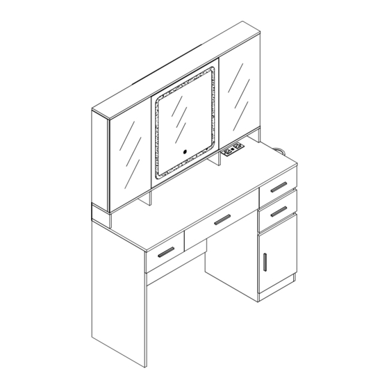
JY9940BS01
As this item contains many parts, please read the installation
instruction carefully before installation . Please use tools
properly and carefully. If you have any questions about the
product and installation, please contact us.
service@vabchesofficial.com
Our professional after-sales team will serve you online all
day.
1-46
Advertisement

Related Manuals for VABCHES JY9940BS01


Summary of Contents for VABCHES JY9940BS01
- Page 1 JY9940BS01 As this item contains many parts, please read the installation instruction carefully before installation . Please use tools properly and carefully. If you have any questions about the product and installation, please contact us. service@vabchesofficial.com Our professional after-sales team will serve you online all day.
- Page 2 Before You Start Read through each step carefully and follow the proper order Separate and count all your parts and hardware Give yourself enough room for the assembly process Have the following tools: Flat Head Screwdriver, #2 Phillips Head Screwdriver and Hammer Caution: If using a power drill or power screwdriver for screwing, please be aware of to slow down and stop when screw is tight.
- Page 3 Board ldentification Not actual size 3 x1 1 x1 2 x1 Lower middle partition Lower left panel Panel 4 x1 5 x1 6 x1 Lower right panel Lower neutral plate Rear pull-up bar 7 x2 8 x1 9 x2 Rear dropdown bar Front dropdown bar Kickboard&Rear Brace 10 x2...
- Page 4 Board ldentification Not actual size 19 x1 20 x1 21 x1 Shelving partition Shelving partition Movable Shelf 22 x4 23 x1 24 x1 Desktop partition Right jewelry box layer boards Upper back plate 25 x1 26 x1 27 x1 Lower back panel Backboard clamp strip Left back panel 28 x1...
- Page 5 Board ldentification Not actual size 37 x1 38 x1 39 x1 Dresser panels Rear panel of drawe Left drawer panel 40 x1 41 x2 42 x4 Right drawer panel Middle drawer panel Drawer left panel 43 x4 44 x3 45 x3 Small drawer bottom panel Small drawer back panel Drawer right panel...
- Page 6 Part List Ø4x35mm Ø3.5x12mm Ø6x30mm Ø15x10mm Ø6x35mm x68(+5) x65(+2) x65(+2) x58(+4) x74(+4) Flat Head Cam Bolt Sliding Track Screw Cam Lock Dowel Tapping Screw Ø3x12mm x10(+2) x30(+3) A Hook Lamina Torus Backboard screws Strip Screw Ø6x30mm Ø4x14mm Ø3x16mm Anti-Fall Strip Rebound device Back Buckle Round head screw...
- Page 7 Part List Cam Lock Fastening System Insert the cam bolt into the hole first, then insert the cam lock and lock it. The opening must point toward the edge of the board 7-46...
- Page 8 Board ldentification Not actual size 20 18 25 21 8-46...
- Page 9 STEP 1 Ø3.5x12mm Ø6x35mm L300mm L300mm 9-46...
- Page 10 STEP 2 Ø3.5x12mm L300mm L300mm Flip Flip 10-46...
- Page 11 STEP 3 Ø6x35mm Flip 11-46...
- Page 12 STEP 4 Ø6x30mm Ø15x10mm Proper orientation of CAM LOCK 12-46...
- Page 13 STEP 5 Ø6x30mm Ø4x35mm 13-46...
- Page 14 STEP 6 Ø6x30mm Ø15x10mm Ø4x35mm Proper orientation of CAM LOCK 14-46...
- Page 15 STEP 7 15-46...
- Page 16 STEP 8 Ø6x30mm Ø4x35mm Ø6x35mm 16-46...
- Page 17 STEP 9 Ø6x30mm Ø15x10mm Proper orientation of CAM LOCK 17-46...
- Page 18 STEP 10 Ø4x12mm Ø3x16mm 18-46...
- Page 19 STEP 11 Ø3x12mm R x1 S x2 19-46...
- Page 20 STEP 12 Move the black paddle upward and pull out (X-2) to the right. 20-46...
- Page 21 STEP 13 Ø3.5x12mm 21-46...
- Page 22 STEP 14 Ø3x12mm Ø6x35mm Ⅱ Ⅰ 22-46...
- Page 23 STEP 15 Ø6x30mm Ø15x10mm Proper orientation of CAM LOCK 23-46...
- Page 24 STEP 16 Ø6x30mm Ø4x35mm 24-46...
- Page 25 STEP 17 Ø6x30mm Ø4x35mm 25-46...
- Page 26 STEP 18 Ø6x30mm Ø4x35mm 26-46...
- Page 27 STEP 19 Ø6x35mm 27-46...
- Page 28 STEP 20 Ø15x10mm Proper orientation of CAM LOCK Need Two or More People To Complete 28-46...
- Page 29 STEP 21 29-46...
- Page 30 STEP 22 Ø4x12mm Ø3x12mm W x8 30-46...
- Page 31 STEP 23 To adjust the vertical height. Loosen the four screws "A" on both hinges. Two of them are usually in slotted holes which allows you to adjust up or down by a few mm. Then tighten back up. To adjust depth. Loosen screw "B"...
- Page 32 STEP 24 Ø4x12mm W x8 32-46...
- Page 33 STEP 25 Ø4x12mm W x8 T x1 If you find that the elastomer can not be adsorbed when the installation is complete, please adjust here a little, as shown 33-46...
- Page 34 STEP 26 Ø3x12mm Ø6x35mm 34-46...
- Page 35 STEP 27 Ø4x35mm 35-46...
- Page 36 STEP 28 Ø6x30mm 36-46...
- Page 37 STEP 29 Ø6x30mm Ø15x10mm Proper orientation of CAM LOCK 37-46...
- Page 38 STEP 30 Ø3.5x12mm 38-46...
- Page 39 STEP 31 Q x18 If you find that the elastomer can not be adsorbed when the installation is complete, please adjust here a little, as shown 39-46...
- Page 40 STEP 32 Ø4x35mm 40-46...
- Page 41 STEP 33 41-46...
- Page 42 STEP 34 Ø6x35mm 42-46...
- Page 43 STEP 35 Ø15x10mm Proper orientation of CAM LOCK 43-46...
- Page 44 STEP 36 Ø3.5x12mm L300mm L300mm 44-46...
- Page 45 STEP 37 45-46...
- Page 46 STEP 38 Ø6x30mm Ø4x35mm WALL WALL WALL drilling hole Ø6x30mm WALL Power supply 46-46...