Table of Contents
Advertisement
Quick Links
Air Flow Monitoring
Operating Instructions for the Air Flow
Sensors and Monitors of Series F3.xEx and
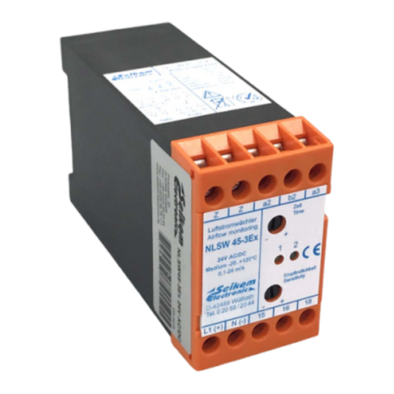
NLSW45-3Ex (Gg)
The person installing the devices as well as the system operator are obligated to ensure the satisfaction of the
mandatory national ex-legislation. Electrostatic charges on plastic parts and wires must be avoided. The
devices must be protected from any damage. The wire connecting the flow sensor must be attached to
stationary surfaces and must be protected from any harm. Stray radiation must be avoided.
Our products satisfy the requirements specified in the European directives WEEE 2012/19/EU and
RoHS 2011/65/EU.
SEIKOM-Electronic GmbH & Co. KG – Fortunastr. 20 – 42489 Wülfrath – Germany
Phone: +49(0)20 58 / 20 44 –
– Email: info@seikom-electronic.com
www.seikom-electronic.de
Advertisement
Table of Contents

Subscribe to Our Youtube Channel
Related Manuals for Seikom Electronic NLSW45-3Ex


Summary of Contents for Seikom Electronic NLSW45-3Ex
- Page 1 Operating Instructions for the Air Flow Sensors and Monitors of Series F3.xEx and NLSW45-3Ex (Gg) The person installing the devices as well as the system operator are obligated to ensure the satisfaction of the mandatory national ex-legislation. Electrostatic charges on plastic parts and wires must be avoided. The devices must be protected from any damage.
-
Page 2: Table Of Contents
Troubleshooting ..........................8 Disposal .............................. 8 Labelling of the Air Flow Sensors F3.xEx ..................8 Technical Data of the Air Flow Monitors NLSW45-3Ex ..............9 Installation of the Air Flow Monitors NLSW45-3Ex ................ 9 Start-Up and Switch-Point Adjustment ..................10 SEIKOM-Electronic GmbH & Co. KG – Fortunastr. 20 – 42489 Wülfrath – Germany Phone: +49(0)20 58 / 20 44 –... -
Page 3: Preamble
The permissible ambient temperature range for the air flow sensor is 0 °C ≤ Ta ≤ 60 °C. The permissible ambient temperature range for the NLSW45-3Ex is -20 °C ≤ Ta ≤ 50 °C. The permissible media temperature (air flow sensor) is 0 °C ≤ T ≤ 60 °C. -
Page 4: Electrical Specifications For Ex-I
Air Flow Monitoring Operating Instructions for the Air Flow Sensors and Monitors of Series F3.xEx and NLSW45-3Ex Electrical Specifications for Ex-i When installing, please note that the Z-barriers BZE804 and 805 have different values! If the barriers are swapped, the air flow monitor NLSW45-3Ex will not function properly! -
Page 5: Sensor Properties For Series F3.Xex
Air Flow Monitoring Operating Instructions for the Air Flow Sensors and Monitors of Series F3.xEx and NLSW45-3Ex Sensor Properties for Series F3.xEx Type F3Ex F3.1Ex F3.2Ex F3.3Ex Article-No 50276/ex 50276/130/Ex 50276/150/Ex 50276/300/Ex Approx. immersion depth 50 mm 130 mm 165 mm... -
Page 6: F3.2Ex
Air Flow Monitoring Operating Instructions for the Air Flow Sensors and Monitors of Series F3.xEx and NLSW45-3Ex 2.5.3 F3.2Ex 2.5.4 F3.3Ex Design like F3.2Ex, but immersion depth 300mm. The drawing will be available in the near future. Temperature Class The sensors are suitable for use with temperature class T4. -
Page 7: Installation And Start-Up
Air Flow Monitoring Operating Instructions for the Air Flow Sensors and Monitors of Series F3.xEx and NLSW45-3Ex i) The person performing the installation of the air flow sensors and their connection to the flow monitors is responsible for their correct function and must ensure that they are eligible for their intended use. -
Page 8: Installation Conditions Of The Air Flow Sensors F3.Xex
Air Flow Monitoring Operating Instructions for the Air Flow Sensors and Monitors of Series F3.xEx and NLSW45-3Ex The following conditions must be met: a) Installation and maintenance may only be executed in atmospheres without any explosion hazard and in compliance with the applicable national regulations depending on the location of operation. -
Page 9: Maintenance And Service
Air Flow Monitoring Operating Instructions for the Air Flow Sensors and Monitors of Series F3.xEx and NLSW45-3Ex 4. Maintenance and Service Definitions Definitions according to IEC 60079-17: Maintenance and Repair: A combination of activities, carried out to maintain an object in a certain condition or to regain this condition, which satisfies the requirements of the relevant specifications and ensures the ability to perform the demanded functions. -
Page 10: Troubleshooting
Air Flow Monitoring Operating Instructions for the Air Flow Sensors and Monitors of Series F3.xEx and NLSW45-3Ex 5. Troubleshooting Products used in areas exposed to explosion hazards cannot be altered or modified. Repair of the product can only be performed by qualified and authorised personnel which has received specialised education in this field. -
Page 11: Technical Data Of The Air Flow Monitors Nlsw45-3Ex
9. Installation of the Air Flow Monitors NLSW45-3Ex The air flow monitors of the series NLSW45-3Ex must be mounted, together with the safety barriers, outside of the area exposed to an explosion hazard. The protection class IP40 of the housing must be considered. -
Page 12: Start-Up And Switch-Point Adjustment
ATTENTION: It is not permitted to connect the connection “N” of the supply voltage with b2 (strand no. 2) of the sensor wire when using a 24 AC and DC air flow monitor of the series NLSW45-3Ex! Start-Up and Switch-Point Adjustment The relation between air flow velocity and resistance change is non-linear.
Need help?
Do you have a question about the NLSW45-3Ex and is the answer not in the manual?
Questions and answers