Table of Contents
Advertisement
Quick Links
Advertisement
Table of Contents

Related Manuals for Avid Technology Stage 48


Summary of Contents for Avid Technology Stage 48
- Page 1 Stage 48 for VENUE Systems PN 9320-65036-00 REV A 2/12...
- Page 2 MasterMeter, TL Metro, TL Space, TL Utilities, Transfuser, Trillium Lane Labs, Vari-Fi, Velvet, X-Form, and XMON are trademarks or registered trademarks of Avid Technology, Inc. Xpand! is Registered in the U.S. Patent and Trademark Office. All other trademarks are the property of their respective owners.
-
Page 3: Table Of Contents
Chapter 4. Configuring and Installing I/O in Stage 48 ....... . - Page 4 Stage 48...
-
Page 5: Chapter 1. Introduction
You can also purchase an empty Stage 48 and expand your sys- tem’s remote I/O capabilities by installing compatible VENUE Stage I/O cards in Stage 48 (up to the maximum Stage I/O ca- Additional Required Components pacity of SC48–48 input channels and 32 output channels of combined local and remote Stage I/O). -
Page 6: Operational Requirements
Cleaning and Maintenance VENUE-specific webinars to learn from the experts. If you need to clean the surface of the Stage 48, use a dry cloth. To learn more about these and other resources available from Do not apply any cleaning solutions, spray cleaners, or abra- Avid, visit our website (www.avid.com). -
Page 7: Conventions Used In This Guide
Conventions Used in This Guide All of our guides use the following conventions to indicate menu choices and key commands: Convention Action Options > System In the VENUE software, click Options to display the Options page, then click the System tab. File >... - Page 8 Stage 48...
-
Page 9: Chapter 2. Overview
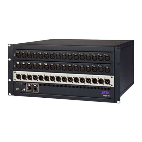
Chapter 2: Overview This section describes the front and back panel features of Stage 48, and the front panel features of the Ethernet Snake card that is installed in SC48. Stage 48 If you purchased an SC48 Remote system, a fully populated Stage 48 with two AI16 Analog Input cards and one AO16 Analog Out- put card is included. - Page 10 (Act) and Signal (Sig) LEDs. The system is ready for use cate the status of Stage 48. when all Stage 48 units are connected and all Act and Sig LEDs See “Power and Status LED Indicators” on page 21 for are lit solid.
- Page 11 AC power connector Figure 2. Stage 48 back panel Power Switch The Power switch applies power to the Stage 48. AC Power Connector The AC power connector accepts a standard IEC AC power ca- ble. The Stage 48 is auto-power selecting (100VAC to 240VAC).
-
Page 12: Ethernet Snake Card
(5) seconds puts Stage 48 into firmware update mode. Stage 2 Ports A and B When using a second Stage 48, Stage 2 port A is used for the Check www.avid.com/support for VENUE support, in- primary snake connection and port B is for the redundant cluding Stage 48 firmware downloads and firmware up- snake connection. -
Page 13: Chapter 3: Connecting Stage 48 9
Before connecting and powering up your system, you must set is important to follow the proper power up sequence. your the device ID of any Stage 48 units you will be connecting to SC48. To make snake connections and power up your system:... -
Page 14: Confirming I/O
Connect the included IEC power cable(s) between the Power connector(s) on any Stage 48 units present and your power source. Press the Power switch on the first Stage 48 to power on the device. The Status LED indicator is lit solid yellow while the Stage 48 initializes. -
Page 15: Chapter 4. Configuring And Installing I/O In Stage 48
SC48 Remote system. Converting your SC48 lets you connect tions are possible. The only requirement is that the top two your SC48 to up to two Stage 48 units. In order to convert your AI16 output cards must be removed when converting an SC48, the top two AI16 input cards must be removed from SC48 to an SC48 Remote system. -
Page 16: Removing I/O Cards From Sc48
SC48 Stage I/O cards that you want to relocate to one or to two Stage 48 units can be removed from SC48 prior to sending it to an Avid-authorized service technician. You can then install these cards in Stage 48. - Page 17 Loosen the two interior captive thumbscrews that secure the card to the console chassis. Output cards can be removed from SC48 and installed in Stage 48. The following procedure shows how to remove an output card from slot D of SC48. To remove an AO16 card: Remove the 26 screws that secure the Top Panel to the con- sole chassis.
- Page 18 Disconnect the 50-pin ribbon cable by pushing the retaining clips outwards. Note the location and orientation of the cable. Figure 13. Disconnecting the 50-pin ribbon cable Leave the disconnected ribbon cable in the console. Do not attempt to remove it. Stage 48...
-
Page 19: Installing I/O Cards In Stage 48
50-pin ribbon cables located in- side Stage 48. I/O cards can be installed in any slot of Stage 48, in any order. If you are installing a combination of input and output cards, however, it is recommended that you install input cards above output cards. - Page 20 Inside Stage 48, locate the pre-installed 50-pin I/O card rib- • For a card installed in the top slot of Stage 48, use the ca- bon cable bundle. ble that is labeled in Figure 22 as “1.”...
-
Page 21: Installing Stage 48 In A Rack
Installing Stage 48 in a Rack Stage 48 can be installed in a standard 19-inch rack. When in- stalling Stage 48 in a rack, it is recommended that you install the included rear brackets for stability. Your rack must be equipped with rear rack rails. - Page 22 Stage 48...
-
Page 23: Chapter 5. Specifications
Chapter 5: Specifications Supported Stage I/O Card Audio Specifications AI16 Analog Input Card Parameter Specifications Limit Units Condition/Comment Type Balanced, XLR3-Female Gain +10 to +60 6 dB analog steps with 0.1 dB dig- ital increments and crossfade at analog relay switch point Max Input Level Pad ON Input Impedance, pad OFF... -
Page 24: Stage 48 Mechanical Specifications
All measurements at Fs=48 kHz with 150 Ohm source impedance and 600 Ohm load impedance, unless otherwise specified. 0 dBU = 0.775Vrms. Stage 48 Mechanical Specifications Stage 48 Specifications Dimensions (H x W x D) 8.75 x 17.05 x 18 inches (222 x 433 x 455 mm) without ears 8.75 x 19 x 18 inches (222 x 481 x 455 mm) with ears... -
Page 25: Power And Status Led Indicators
Power LED Indicator (Stage 48 and Ethernet Snake Card) (Stage 48 Only) The Status LEDs on the Ethernet Snake Card and the Stage 48 The Power LED lights to indicated the power status of Stage 48 light to indicate status as follows:... - Page 26 Stage 48...
-
Page 27: Appendix A. Compliance Information
Appendix A: Compliance Information FCC Compliance for United States Environmental Compliance Radio and Television Interference Disposal of Waste Equipment by Users in the European Union Communication Statement NOTE: This equipment has been tested and found to comply with the limits for a Class B digital device, pursuant to Part 15 of the FCC Rules. -
Page 28: Safety Compliance
1) Read these instructions. 7) For products with a power switch: 2) Keep these instructions. The main power switch is located on the back panel panel of the Stage 48. It should remain accessible after installation. 3) Heed all warnings. - Page 29 Avid Technical Support (USA) Product Information 2001 Junipero Serra Boulevard Visit the Online Support Center at For company and product information, Daly City, CA 94014-3886 USA www.avid.com/support visit us on the web at www.avid.com...
Need help?
Do you have a question about the Stage 48 and is the answer not in the manual?
Questions and answers