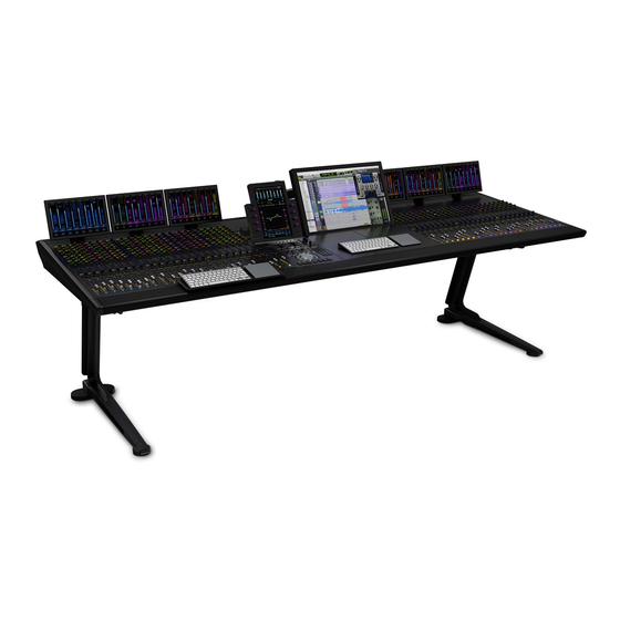
Avid Technology Pro Tools S6 Assembling/Disassembling
Expanding
Hide thumbs
Also See for Pro Tools S6:
- Installation manual (92 pages) ,
- User manual (20 pages) ,
- Manual (20 pages)
Table of Contents
Advertisement
Quick Links
Advertisement
Table of Contents

Related Manuals for Avid Technology Pro Tools S6


Summary of Contents for Avid Technology Pro Tools S6
- Page 1 Expanding an S6 System...
- Page 2 Legal Notices © 2015 Avid Technology, Inc., (“Avid”), all rights reserved. This guide may not be duplicated in whole or in part without the written consent of Avid. 003, 192 Digital I/O, 192 I/O, 96 I/O, 96i I/O, Adrenaline, AirSpeed, ALEX,...
-
Page 3: Table Of Contents
Contents Part I Introduction Chapter 1. Introduction ................2 . - Page 4 Part I: Introduction...
-
Page 5: Chapter 1. Introduction
Chapter 1: Introduction ® This guide provides instructions for disassembling a Pro Tools | S6 in order to move or expand the system. Important Before you begin: • Make sure you have a padded tabletop or other flat surface nearby to place components and modules as they are removed. •... -
Page 6: Overview Of Disassembly For Moving, Customizing Or Expanding A System
Overview of Disassembly for Moving, Customizing or Expanding a System S6 systems can be customized by adding hardware options, disassembled for moving, and expanded by adding modules or chassis. Customizing a System with Hardware Options You can add any of the following hardware options to S6 M10 or M40 systems: •... -
Page 7: About This Guide
About This Guide This section describes elements of this guide, and provides tips for navigating and searching. Conventions Used in This Guide All of our guides use the following conventions to indicate menu choices and key commands: Convention Action Settings > Surface Navigate the Master Module to the Settings screen, then tap to select the Surface page Control+N Hold down the Control key and press the N key... -
Page 8: Resources
Resources The Avid website ( ) is your best online source for information to help you get the most out of your Avid system. www.avid.com The following are just a few of the services and features available. Account Activation and Product Registration Activate your product to access downloads in your Avid account (or quickly create an account if you don’t have one). -
Page 9: Part Ii Disassembly
Part II: Disassembly... -
Page 10: Chapter 2. Initial Disassembly
Chapter 2: Initial Disassembly This section explains how to do the following initial disassembly steps, all of which are required whether you are moving or ex- panding a frame: • Updating the Surface Settings • Shutting Down the System • Removing Hardware Options •... -
Page 11: Shutting Down The System
Shutting Down the System To shut down the system: Navigate the Touchscreen to Settings > About page, then touch Shut Down . Wait until the Master Module has completely shut down before proceeding. Always shut down the Master Module from the About page before powering down the system! Turn off the source that supplies power to the S6 Power Strip (UPS, power conditioner or other). -
Page 12: Removing Display Modules
Removing Display Modules If your M40 system includes Display Modules, remove them next. Otherwise, proceed to “Removing T-Strips” on page 9 To remove Display Modules: Disconnect power and Ethernet cables connected to the Display Modules. While holding the Display Module with one hand, remove the four fasteners that secure the first Display Module to its mounting bracket. -
Page 13: Removing Compression Panels And Fill Panels
Removing Compression Panels and Fill Panels To remove Compression Panels: Remove Compression Panels from the top-most slot of each chassis. Push them gently towards the back of the console to com- press their built-in springs, then lift out the front edge and remove the panel. Figure 4. -
Page 14: Chapter 3. Removing Modules And Disconnecting Cabling
Chapter 3: Removing Modules and Disconnecting Cabling This section explains how to remove modules and cables. It is recommended that you remove all modules and Cable Sets from the system before disassembling a frame to move it or to ex- pand it. -
Page 15: Disconnecting Cable Sets
Disconnecting Cable Sets To disassemble a frame to move or expand a system, you should disconnect and remove all Cable Sets. To disconnect Cable Sets: Standing behind the system, start at either end and disconnect the Ethernet Cable Set from the back of the first chassis (far left or far right). -
Page 16: Chapter 4. Detaching Chassis
Chapter 4: Detaching Chassis This section explains how to determine which chassis to detach in order to move or expand a frame, and shows you how to remove frame components and detach chassis. Components and systems are heavy! We recommend using four people, one to lift each corner. Never attempt to move a system that is five or more chassis in width. - Page 17 Disassembling Avid Configurations Use these diagrams to determine which chassis to detach, then proceed to “Disassembling a Frame” on page 16 . For larger cus- tom configurations see “Disassembling Custom S6 Configurations” on page 15 The following diagrams do not show cable harnesses, Rear Cover brackets, Side Covers, or the Producers Desk option. If your system includes a Producers Desk, it counts as two chassis when determining system width.
- Page 18 Disassembling Custom S6 Configurations These diagrams show where to detach chassis to move or expand systems that are six or more chassis in width. 6-Chassis Figure 6. Where to detach chassis to move or expand a six-chassis frame 7-Chassis Figure 7. Where to detach chassis to move or expand a seven-chassis frame 9-Chassis 9-Chassis systems require two pairs of chassis to be detached before moving.
-
Page 19: Disassembling A Frame
Disassembling a Frame After determining which chassis you need to detach, disassemble the frame as described in the following instructions. Make sure you have already removed modules and connectivity components as instructed in Chapter 3, “Removing Modules and Discon- necting Cabling.” As you disassemble frame components, keep all fasteners organized to simplify re-assembly. - Page 20 Remove the four Phillips screws that secure the right Side Cover to the frame (see Figure 11). Fastener M4x14 FHPH Tool #2 Phillips (Not to scale) Figure 11. Removing the right Side Cover Side Covers when Expanding a System If you are adding a single chassis to a Leg Frame system, or if your system (desktop or Leg Frame) shipped from the factory before July 2, 2014, you must replace your existing Bolster.
- Page 21 Removing the Bolster Remove the Bolster (arm rest) by unscrewing its fasteners and lifting it off the front edge of the frame. Have someone hold the Bolster in place while you remove the fasteners to prevent it from falling on you. To remove the Bolster: From underneath the Bolster, remove all Hex fasteners that secure it to the frame.
- Page 22 Removing the Rear Cover Mounting Brackets Remove the Rear Cover Mounting Bracket attached to each pair of chassis to be detached. You do not need to remove all Rear Cover Mounting Brackets. To remove the Rear Cover Mounting Brackets: Standing at the back of the frame, identify the Rear Cover Mounting Bracket attached to each pair of chassis to be detached. Remove the two Hex fasteners and washer securing the Rear Cover bracket to the Back Tie Plates of the two chassis (see Figure 13).
- Page 23 Detaching Chassis To detach chassis from each other, you must remove seven fasteners. To detach chassis: Remove the Hex fasteners that secure the Front and Back Tie Plates to the adjacent chassis Side Wall (see Figure 15). Fastener M5x8 FHCS (7760-30553-00) Tool M3 Hex (Not to scale)
-
Page 24: How To Proceed
How to Proceed If your system includes a Leg Frame, proceed to Chapter 5, “Disassembling and Expanding Leg Frames.” If not, do either of the following. To move an existing system: Move each chassis section (and Leg Frame if applicable) following all the previously listed precautions. After the components are in their new location, re-assemble Legs (if any) and chassis, then reinstall Cable Sets, modules, and other hardware components. -
Page 25: Chapter 5. Disassembling And Expanding Leg Frames
Chapter 5: Disassembling and Expanding Leg Frames This section describes how to disassemble and expand Leg Frames. Before you begin, make sure you have removed all modules, cables, and chassis as described in previous sections of this guide. Components and systems are heavy! We recommend using four people, one to lift each corner. Never attempt to move a system that is five or more chassis in width. -
Page 26: Detaching Leg Frame Join Modules
Detaching Leg Frame Join Modules To detach Leg Frames that include a Leg Frame Join Module: Detach the left frame from the bracket by removing the eight fasteners and washers (see Figure 18). (Not to scale) M5x15 (7760-30604-00) Fastener Washer M5 WSHR (7760-30607-00) Tool M4 Hex... - Page 27 Expanding a Frame with Leg Frame Extensions If you are expanding your system by adding one or more Leg Frame Extensions, install them now. To install Leg Frame Extensions: Attach any Leg Frame Extension(s) as shown in Figure 20. (Not to scale) Fastener M5x15 (7760-30604-00) Washer...
-
Page 28: Removing The Back Corner Brackets
Removing the Back Corner Brackets If you are disassembling the Leg Frame to move or expand it, detach or remove the Back Corner Brackets. To remove the Back Corner Brackets: Detach the Back Corner Brackets from the legs (see Figure 21) by removing the four fasteners and washers per bracket. ... -
Page 29: How To Proceed
Expanding a Frame with Leg Frame Join Modules The Leg Frame Join Module consists of special center Legs and a mounting bracket that let you join two or more S6 Leg Frames together to form a larger system. The center Legs provide frame support with a shorter bottom foot than standard Leg Frame Legs. The bracket attaches to the Beams to join the two frames together. -
Page 30: Part Iii Appendix
Part III: Appendix... -
Page 31: Appendix A. Labels For Fasteners
Appendix A: Labels for Fasteners To help keep fasteners organized, print these pages, cut out the labels, and place them in containers for each type of fastener. Display Modules Bolster M4x10 BCHS Fastener (7760-30535-00) Fastener M5x10 BHCS (7760-30615-00) Tool M2.5 Hex Tool (Not to scale) M3 Hex... - Page 32 Chassis Hex Chassis Phillips (Not to scale) (Not to scale) Fastener M3x6 SEMS (7760-30025-01) Fastener M5x8 FHCS (7760-30553-00) Tool #1 Phillips Tool M3 Hex Leg Frame End Brackets Leg Frame Back Corner Brackets (Not to scale) Fastener M5x15 (7760-30604-00) Fastener M5x15 (7760-30604-00) Washer M5 WSHR (7760-30607-00)
- Page 34 Avid Technical Support (USA) Product Information 280 N Bernardo Avenue Visit the Online Support Center at For company and product information, Mountain View, CA 94043 USA www.avid.com/support visit us on the web at www.avid.com...
Need help?
Do you have a question about the Pro Tools S6 and is the answer not in the manual?
Questions and answers