Avid Technology Venue S6L System Manual
Hide thumbs
Also See for Venue S6L:
- Installation manual (87 pages) ,
- Handbook (40 pages) ,
- Quick start manual (11 pages)
Table of Contents
Advertisement
Quick Links
Advertisement
Table of Contents

Related Manuals for Avid Technology Venue S6L


Summary of Contents for Avid Technology Venue S6L
- Page 1 Avid VENUE | S6L System Guide and Avid VENUE | Software 6.1...
- Page 2 Legal Notices © 2019 Avid Technology, Inc., (“Avid”), all rights reserved. This guide may not be duplicated in whole or in part without the written consent of Avid. For a current and complete list of Avid trademarks visit: http://www.avid.com/legal/trademarks-and-other-notices Bonjour, the Bonjour logo, and the Bonjour symbol are trademarks of Apple Computer, Inc.
- Page 3 2013-07-24, CAN/CSA C22.2 No. 60065-03, 1st Ed, +A1:2006 +A2:2012, EN 60065:2002 +A1:2006 +A11:2008 +A2:2010 +A12:2011, IEC 60065:2001 +A1:2005 +A2:2010. Avid Technology Inc., has been authorized to apply the appropriate NRTL mark on its compliant equipment. Safety Statement: (M/N: E6L(all)) This equipment has been tested to comply with USA and Canadian safety certification in accordance with the specifications of UL Standards: UL 60950-1 2nd edition, CAN/CSA C22.2 No.
- Page 4 16) For products containing a lithium battery: Warning! Danger of explosion if battery is incorrectly replaced. Replace only with the same or equivalent type. 17) For products with a power switch: It should remain accessible after installation. 18) The equipment shall be used at a maximum ambient temperature of 40° C and maximum altitude of 2000m. 19) This unit may not ship with a power supply cord set.
-
Page 5: Table Of Contents
Contents Part I Overview Introduction to the VENUE | S6L System ............1 Installation and Setup . - Page 6 Part II Using S6L Configuring System Audio ............... 61 Powering the System Up and Down .
- Page 7 VCAs Trim Aux Sends in Sends on Faders Mode ..........144 Adjusting Aux Sends on the External Screen .
- Page 8 Working with Presets ............... 206 Transferring Settings, Shows and Presets .
- Page 9 Tap Tempo for Plug-ins ..............294 WSG-HD Waves SoundGrid Option Card and Waves Plug-Ins .
- Page 10 Hardware Inserts ................372 Connecting External Hardware .
- Page 11 Output Channel Signal Flow ..............411 Part VII Appendices Environmental Compliance .
- Page 12 Part I: Overview...
-
Page 13: Introduction To The Venue | S6L System
Ethernet network. For more information see ECx Ethernet Control ECx Ethernet Control Guide. Installation and Setup For complete hardware and software installation instructions, see the VENUE S6L Installation Guide.pdf, available for download from your and from the article on our Knowledge Base. -
Page 14: S6L Control Surface Features
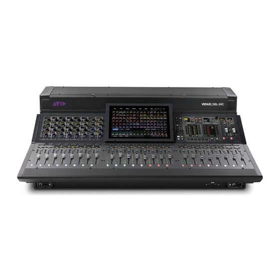
S6L System Recording and Playback Features • 128 channels of recording and playback (64 in x 64 out) with a compatible Pro Tools system, including true Virtual Sound- check capability. Or with two compatible Pro Tools systems, one recorder (up to 128 channels) and one record/playback sys- tem. - Page 15 S6L-32D VENUE | S6L-32D S6L-24D VENUE | S6L-24D S6L-24C VENUE | S6L-24C Introduction to the VENUE | S6L System...
- Page 16 S6L-16C VENUE | S6L-16C Lights (S6L-24C and S6L-16C) The S6L-24C provides 2x connectors (3-pin XLR) on the top panel for connecting goose-neck LED console lamps. Note that only LED lights are supported on the S6L-24C. S6L-32D and S6L-24D control surfaces provide a built-in Light Bar to illuminate the surface.
-
Page 17: E6L Engine Features
E6L Engine Features The E6L engine provides the real-time processing engine for input and output channels, and Pro Tools | HDX DSP processing card(s) for AAX DSP plug-ins. The E6L engine also provides connections for synchronization, control and utility in a 5U rack-mountable enclosure. -
Page 18: Stage 64 I/O Rack Features
Stage 64 I/O Rack Features Stage 64 provides remote stage I/O for S6L systems in a 10U rack-mountable enclosure. The S6L system supports redundant audio network connections to up to three Stage 64 I/O racks. Audio network connections are made using supported copper Ethernet ca- bles and/or fiber-optic cables (see Audio Network Connections I/O Rack... -
Page 19: Stage 32 I/O Rack Features
Stage 32 I/O Rack Features Stage 32 provides remote stage I/O for S6L systems in a 5U rack-mountable enclosure. Up to four Stage 32 units can be connected on supported systems. Audio snake connection are made using supported Ethernet cables (see Audio Network Connections Stage 32 requires 2x AVB-192 Network Cards in the E6L engine. -
Page 20: Stage 16 Remote Io Features
Stage 16 Remote IO Features Stage 16 provides remote stage I/O for S6L systems in a 4U rack-mountable enclosure. Up to four Stage 16 boxes can be connected on supported systems. Audio snake connection are made using supported Ethernet cables (see Audio Network Connections Stage 16 requires 2x AVB-192 Network Cards in the E6L engine. -
Page 21: Local 16 I/O Features
Rack spaces Local 16 I/O What’s Included See the VENUE S6L Installation Guide.pdf for a complete list of what’s included with each system, additional required items (re- quired but not included), and optional items. Introduction to the VENUE | S6L System... -
Page 22: Expansion Options
Up to four Stage 32 units can be networked at once (requires dual AVB-192 Network Cards in the E6L engine), and you can com- bine Stage 32 with other VENUE S6L I/O units up to the maximum capacity of your system configuration. For requirements and connection diagrams see the VENUE S6L Installation Guide.pdf. -
Page 23: Operational Requirements
Operational Requirements Temperature and Ventilation S6L system devices should be operated away from heat sources and with adequate ventilation. Hardware monitoring and automatic warnings are provided for temperature, power and other factors. For more information, Hardware Monitoring Window Storage S6L system devices should be stored and transported at temperatures not lower than 0 degrees F (–18 degrees C) and not exceeding 140 degrees F (60 degrees C). -
Page 24: Cabling Requirements
S6L system components can be made using either copper or fiber-optic audio network cables. Cable types can be mixed within a system, but only one type of connection (copper or fiber) can be used per audio network connection. For complete information on connecting S6L system components, see the VENUE S6L Installation Guide.pdf. Copper Shielded Cat 5e (350 MHz) or better Ethernet cable with Neutrik etherCON connectors are required, supporting a distance of up to 100 meters per connection. -
Page 25: Resources
Resources The Avid website ( ) is your best online source for information to help you get the most out of your Avid system. www.avid.com The following are just a few of the services and features available. Account Activation and Product Registration Activate your product to access downloads in your Avid account (or create an account if you don’t have one). -
Page 26: Conventions Used In This Guide
Conventions Used in This Guide All of our guides use the following conventions to indicate touch screen gestures and key commands: Convention Action Touch Touch an element on-screen briefly and immediately release your finger. Used to activate a function or toggle a parameter value. Swipe Touch an area on-screen and drag left/right/up/down. -
Page 27: S6L Control Surface Overview
S6L Control Surface Overview The section provides an overview of S6L control surface controls, and front and back panel audio, control, and power connections. S6L Control Surface Top Panel Overview The S6L control surface is available in four models, S6L-32D, S6L-24D, S6L-24C, and S6L-16C. Most available controls are com- mon across all models, and only vary in quantity between models. -
Page 28: Fader Banks
Fader Banks Each fader bank provides eight channel strips to control input or output channels, depending on the type Menu Safe of channels banked to the faders. Each channel strip provides the following controls and indicators: Ch 1 CH 1 0.0 dB 1 –... - Page 29 Channel Menu The Channel Menu provides several pages of parameters that apply to the banked channel. The Menu switch (“1” in the figure be- low) enables the Channel Menu, which is shown in the channel display. The Left and Right Menu switches (2 and 3 in the figure below) toggle the currently displayed Channel Menu parameter.
- Page 30 Channel Safe Each channel strip provides a dedicated Channel Safe switch that lets you Automation, Solo (input channels only), or Bank Safe the currently banked channel. The Safe mode engaged by the Channel Safe switch is defined globally for input and output channels in the Channel Safe Switches section of the Options >...
- Page 31 Select Select selects a channel locally, targeting the channel for processing using the 32 encoders on the associated Channel Knob Mod- ule (CKM). From the CKM you can access channel processing functions such as EQ and dynamics via Channel Control mode (see Channel Control Mode for more information).
- Page 32 Channel and Gain Reduction Meters Each channel strip features dual 30-segment signal level meters and a dedicated 10-segment dynamics meter. Channel Level Meter For mono channels, only the left meter shows level. For stereo channels, both meters show signal level. The pickoff point for the input and output channel meters is set on the Options >...
-
Page 33: Channel Knob Modules (Ckm)
Channel Color Switch This switch lights in the color as defined in the external VENUE software (see Color-Coding Channels from the External ) and/or from the Master Touch Screen (see Screen Color-Coding Channel from the Universe View These switches can be customized using Events Channel Knob Modules (CKM) Each Channel Knob Module provides channel parameter control via 32 dual-function encoders that provide switch and rotary func-... - Page 34 Channel Strip Mode Gain Gain Gain Gain Gain Gain Gain Gain Gain Gain Gain Gain Gain Gain Gain Gain When no channels are selected from the corresponding fader bank, the 0.0 dB 0.0 dB 0.0 dB 0.0 dB 0.0 dB 0.0 dB 0.0 dB 0.0 dB...
- Page 35 Channel Control Mode Selecting a channel banked to a fader bank (or touching a parameter touch zone on a Channel Touch Module) enables Channel Con- trol mode on the associated CKM. Channel Control mode provides comprehensive control over parameters such as EQ, Dynamics, plug-ins, and Aux Sends for the currently selected channel.
- Page 36 Channel Control Functions The Channel Control Function switches assign groups of parameters for the currently selected channel to the 32 encoders on the CKM. CHANNEL INPUT DYNAMICS PLUG-INS CKM Channel Control Function Switches The labels below each switch indicate the type of parameters assigned to the CKM, as follows: 1 –...
- Page 37 Encoder Color Coding CKM encoders light in colors according to their function or parameter in all encoder modes, as follows: Function Color Parameter Color Channel Parameters light in the color of the function Group Assign Orange* of which each parameter is a member Input White Mains L-R Assign...
-
Page 38: Channel Touch Module (Ctm)
Channel Touch Module (CTM) The S6L-32D provides three Channel Touch Modules (CTM), and the S6L-24D provides two CTMs. Each CTM is located above a CKM, and is functionally associated with that CKM and the fader bank below it. The CTM provides a local view of the channels banked to the associated fader bank. - Page 39 Channel View (CTM) Touching the Meters in Meters views automatically selects that channel and replaces Meters view with Channel view. Channel view provides a complete view of the selected channel’s parameters. Parameters in each touch zone are lit when that parameter is on, and dimmed when off.
-
Page 40: Master Live Module (Mlm)
6 – Channel Tiles Channel view shows eight channel tiles at a time, mirroring the channels banked to the corresponding fader bank. Each channel tile shows the channel number and name. Touching a channel tile selects that channel, and targets that channel for processing, mirror- ing the function of the channel strip Select switch. - Page 41 Global Modifiers SHIFT Multi-Select (Shift) Multi Multi Select Assgn Multi-Select lets you select or attention multiple channels, and then apply an action to all selected/at- CTRL tentioned channels for batch routing and assignment. For more information see Selecting/Attentioning Default Fine .
- Page 42 Momentary and Latching Modes Fine supports momentary and latching operation. In momentary mode, Fine stays in effect for as long as you hold down that modifier switch. Momentary In latching mode, Fine stays in effect until you explicitly clear its active state. Latching To use Fine in momentary mode: Press and hold Fine .
- Page 43 Prev/Next Switches These switches instantly recall the previous or next snapshot in the Snapshots list. The switches are lit when there is a previous or next snapshot to recall. Store Recall PREV NEXT SNAPSHOTS Prev/Next Snapshot switches System Functions The switches in this section provide control over a variety of system-wide functions. Home Config Over...
- Page 44 Monitoring Section The S6L system provides two discrete Monitor buses (Monitor bus A and B). The Monitoring section provide controls for the cur- rently targeted Monitor bus. Hold SIP Push A/B Mix to Solo Clear MONITORING Monitoring section Monitoring Encoder The monitoring encoder lets you target a Monitor bus for control and provides level control for the targeted Monitor bus, as follows: Push the encoder to toggle the controls in the Monitor section between Monitor bus A and B.
- Page 45 Flex Channels Kick CH 1 Kick Left Two Flex Channels provide access to channels irrespective of the active fader layout or 0.0 dB 0.0 dB 0.0 dB bank. You can configure the Flex Channels in the Fader Configuration section of the Op- tions >...
- Page 46 Fader Banking Controls S6L lets you bank channels to faders in a variety of ways. By default, channels are banked to S6L faders in a “split” banking con- figuration. Input channels are banked sequentially to the fader banks below CKMs and CTMs, and output channels are banked to the fader bank below the MLM.
- Page 47 Left Soft Keys Fader Banking Controls The Left Soft Keys provide access to pre-defined fader bank layouts, as well as custom layouts. The display shows the available fader bank layouts across multiple pages. Pressing a corresponding Soft Key banks the channels indicated in the display to the fad- ers.
- Page 48 Select Clear Clears all selected channels and returns all CKMs to Channel Strip mode. Tap Tempo Sets the system tempo for use as a beat clock for delay and echo plug-ins that support Tempo Sync. The switch blinks in time with the system tempo.
-
Page 49: Master Touch Screen (Mts)
Master Touch Screen (MTS) All S6L control surface models (except the S6L-16C) feature a Master Touch Screen (MTS). Located above the Master Live Mod- ule, the MTS provides a global view of S6L system channels, a Meters view, and can also provide a targeted view of the currently attentioned channel. - Page 50 The Universe view provides the following on-screen elements. Not all elements are available in all Universe views. 1 – Channel Tile Each channel on your system has a corresponding channel tile in the Universe. Each channel tile shows the channel’s number and name, as well as its current attention, mute solo, and favorite status.
- Page 51 To favorite a channel: Tap the Favorite Assign (Star icon) Track Function button on the MTS so it lights. Tap any channel tiles you want to favorite. A star appears in each channel tile that is designated as a favorite. When finished, touch the Favorite Assign button again so it is unlit, or touch another Function Assign button.
- Page 52 Meters View (MTS) The MTS provides a Meters view that looks and operates just like CTM . Meters view provides a local view of the Meters View channels banked to the faders below the MLM. • Tapping a Meter switches the MTS to the Channel view for the corresponding channel. Tapping < returns to Meters view. Meters view on the MTS S6L-24C Meters View on MTS When the MTS is in Meters View it shows the channels on the faders directly below it (OLEDs on those strips show a Selection...
- Page 53 Channel View (MTS) MTS Channel view provides a detailed view of the attentioned channel’s parameters, and provides most of the same on-screen el- ements as the on the CTM. Channel View (CTM) The MTS channel view provides visual feedback for the attentioned channel’s parameters but, unlike the CTM Channel view, pro- vides no touch zones for parameter control.
-
Page 54: S6L Control Surface Connections
S6L Control Surface Connections The S6L-32D, S6L-24D, and S6L-24C, and S6L-16C all have the same network and ancillary connections. Audio connections are identical on all except S6L-16C, as noted below. S6L control surface back panel (S6L-32D/24D/24C) Audio Connections (S6L-32D/24D/24C) S6L control surface audio I/O is assigned to VENUE system channels using the Patchbay, under the Console tab. If using Local 16 I/O, its inputs and outputs appear in the Patchbay under the Local tab. - Page 55 Only one type of connection (copper or fiber-optic) can be active at a time for each port. Never connect both copper and fiber to the same port (A or B). For more information on audio network connections, see the VENUE S6L Installation Guide.pdf. 4 – Network Ports C and D...
- Page 56 9 – Footswitch Connectors 1–2 (2 1/4-inch TRS Connector) Connect footswitches to these connectors. Footswitches can be normally open or normally closed, latching or momentary. Func- tions such as Tap Tempo for delay times are assigned to these connectors using events. See for more information.
- Page 57 3 – PSUs S6L-32D and 24D control surfaces provide dual-redundant hot-swappable PSUs with automatic failover. Each PSU provides an On LED that lights green when the PSU is powered on and functioning properly. S6L-24C and S6L-16C provide dual redundant, internal PSUs. If the On LED does not light when the S6L is powered up, the PSU is faulty and may need to be replaced.
-
Page 58: E6L Engine Overview
E6L Engine Overview The E6L engine provides the real-time processing engine for input and output channels, and Pro Tools | HDX DSP processing card(s) for AAX DSP plug-ins. The E6L engine also provides audio network, synchronization, and utility connections. All E6L en- gine models provide the same connection capabilities. -
Page 59: E6L Front Panel
E6L Front Panel STATUS SYSTEM SHUTDOWN E6L engine front panel The front panel of the E6L engine provides the following controls, connections and indicators: 1 – Status and System LEDs These LEDs indicate the current status of the E6L engine, as described in the following table. Status and System LEDs Color State... -
Page 60: E6L Back Panel
On E6L-112 engines (only) this slot can contain either a second MADI-192 MADI Option card, or a WSG-HD Waves SoundGrid Option card. This slot is not supported in E6L-192 or E6L-144 engines. For more information on audio network connections, see the VENUE S6L Installation Guide.pdf. 2 – Expansion Card Slots The back panel of the E6L engine provides eight half-length PCIe slots for Option cards such as the MADI-192 MADI Option Card. - Page 61 3 – Word Clock In and Out (Two 75 Ohm Coaxial BNC Connectors) These ports let you connect to the word clock ports of external digital devices to sync all digital devices in your system. Clock Synchronization Overview for more information. 4 –...
-
Page 62: Stage And Local I/O Rack Overview
Local 16 can be used with other S6L systems. Integrating Local 16s into S6L systems requires dual AVB-192 Network Cards in the E6L Engine. For example configurations, requirements, and connection diagrams see the VENUE S6L Installation Guide.pdf. Stage and Local I/O Rack Overview... -
Page 63: Stage 64 And Stage 32 I/O Card Features And Capabilities
Stage 64 and Stage 32 I/O Card Features and Capabilities You can install variety of analog and digital I/O cards in Stage 64 and Stage 32. You can purchase a pre-configured unit and modify card configurations, or purchase an empty Stage 64 or Stage 32 and configure your rack as desired. For instructions on installing I/O cards, see the (for Dante card installation, see the S6L Stage I/O Card Installation Guide... -
Page 64: Stage 64 Front Panel
Stage 64 Front Panel The front panel of the Stage 64 provides I/O card slots for I/O cards, and the Stage 64 Controller. +48V +48V +48V +48V +48V +48V MUTE Home > <empty-name> 96k Net OK Mon On HW OK MADI On +48V +48V... - Page 65 Stage 64 Controller All Stage 64 I/O racks include a Controller. The Controller provides the following features: 1 – Status and Fault LEDs Home > These LEDs provide the following indications: <empty-name> 96k Net OK Mon On Indicates the current status of the audio network connection to the Stage 64 Network ports. HW OK MADI On STATUS...
-
Page 66: Making Stage I/O Unit Connections
VENUE software screen to available Stage slots. See the for more information. VENUE S6L Installation Guide.pdf Patching Stage I/O Once you have assigned Stage I/O units to Stage slots, you can then patch Stage I/O to VENUE system channels under the Stage 1–6 tabs in the VENUE Patchbay. - Page 67 Controller Main MENU The main MENU lets you access the MONITOR, SETTINGS, and MUTE menus (via page 1), and the STATUS menu (via page 2). To access the MENU page 1 (MENU 1/2): From the HOME page, press the Display Selector. ...
- Page 68 Controller SETTINGS Menu The SETTINGS menu provides two pages ( SETTINGS 1/2 and SETTINGS 2/2) of configurable Stage 64 parameters, including MADI Out and confidence monitor settings. You can also name and reset the Stage 64. To access the SETTINGS menu: From the HOME page, press the Display Selector.
- Page 69 Resetting Stage 64 To reset the Stage 64 from the Stage 64: With SETTINGS 1/2 highlighted, press the Display Selector to access the second SETTINGS page ( SETTINGS 2/2 ). Rotate the Display Selector so DEVICE is highlighted, then press the Display Selector. Rotate the Display Selector so RESET is highlighted, then press the Display Selector.
- Page 70 Rotate the Display Selector so that STATUS is highlighted, then press the knob. The STATUS menu is shown, and provides pages of options detailing the current status of the Stage 64, as follows: STATUS menu parameters STATUS Menu Parameter Status Description Pages Valid communication exists between this Stage 64 and other...
-
Page 71: Using Madi Outs On Stage 64 And Stage 32
Using MADI Outs on Stage 64 and Stage 32 The two MADI Out connectors on the Stage 64, and the single MADI Out on Stage 32, provide fixed one-for-one digital splits of input channels from the corresponding unit (up to 64 input channels from Stage 64, and up to 32 from Stage 32) at a 48 or 96 kHz sample rate. - Page 72 Part II: Using S6L...
-
Page 73: Configuring System Audio
Enabling Config Mode • Assigning Stage I/O Units • Assigning Local 16 • Setting the System Clock • Configuring Mains and Mix Buses • Managing Connections For complete hardware and software installation instructions. the VENUE S6L Installation.pdf Configuring System Audio... -
Page 74: Powering The System Up And Down
Powering the System Up and Down Use the following instructions to power the system up and down for regular, day-to-day start up and shut down after the system(s) have been connected and configured as explained in the VENUE |S6L Installation Guide. Make sure you have installed the most recent VENUE software. - Page 75 Power on the first Stage I/O unit by pressing the power switch to the On position for the PSU that is plugged into an AC power source. Stage 64: If both PSUs are connected for redundancy, power-on both PSUs. The power switch(es) lights green and the following occurs on the front panel of the Stage 64: •...
-
Page 76: Confirming System Components
Confirming System Components After connecting and powering up system components, you can confirm and configure system components on the Options > Devices page of the VENUE software screen. To confirm system components: On the external screen, select the Options button. Options button Select the Devices tab. -
Page 77: Pairing The E6L And S6L
Pairing the E6L and S6L By default, an E6L engine automatically connects to its previously assigned S6L control surface. When assigned to an E6L, the S6L controls the parameters associated with that E6L. After the initial assignment, an E6L will automatically attempt to reconnect to the most recently assigned S6L. - Page 78 Select CONNECT. Connect button The MTS (or external screen with S6L-16C) indicates that the S6L control surface is waiting for the E6L engine to start. When the devices connect, the Universe view appears on the MTS, and the Inputs page appears on the external screen. If you have incorrectly assigned E6Ls, they must first be unassigned from the S6Ls to which they are currently assigned.
-
Page 79: Enabling Config Mode
Enabling Config Mode There are two main operating modes for the S6L system, Config mode and Show mode. Use Config mode to accomplish tasks such as setting up your system, configuring options, loading Show files, and installing software such as plug-ins and system updates. Use Show mode to mix your performance. -
Page 80: Assigning Stage I/O Units
Assigning Stage I/O Units When you initially configure a system, or after performing a System Restore, you must assign Stage 64, Stage 32, and/or Stage 16 I/O units to available Stage slots in the Options > Devices tab. Each Stage slot corresponds to a Stage hardware tab 1–6 in the VENUE Patchbay. - Page 81 When using more than one type of Stage IO unit, group units by type and connect them in series in the CONNECTED DEVICES column, such as all Stage 64(s), then all Stage 32s, then all Stage 16s. The order of Stage I/O devices in the Connected Devices col- umn does not need to match the order of physical network connections.
- Page 82 Identifying Stage I/O Units It can be helpful to identify each Stage I/O unit in the Available Devices list before assignment. To identify Stage I/O units: Make sure your system is in Config mode. On the external screen, go to the Options > Devices page and locate the Available Devices column. All connected and powered on Stage I/O units are shown in this column.
-
Page 83: Assigning Local 16
Assigning Local 16 Local 16 lets you expand your local I/O capabilities, or add primary local I/O if mixing on the S6L-16C control surface. Each Local 16 provides 8 analog inputs, 8 analog outputs, 8 AES digital inputs, and 8 AES digital outputs in a compact, 3U rack. Local 16 requires 2x AVB-192 Network cards be installed in the E6L engine. - Page 84 Using Master and Slave E6Ls in Shared I/O Configurations (Input and Output Sharing) By default, such as when you first configure systems for I/O Sharing, connecting a Stage device to an E6L engine in the Options > Devices page assigns ownership of all Inputs and Outputs to that E6L (in this context “E6L” is synonymous with “S6L system”).
- Page 85 Before assigning Stage 64s in shared configurations, you should take into account the following differences in functionality be- tween Input Master and Input Slave E6Ls for a connected Stage 64 or Stage 16 (as applicable). Unless otherwise noted, function- ality specified for Stage 64 also applies to Stage 32. Functionality Master E6L Slave E6L...
- Page 86 IO Sharing Example The following diagrams show how shared Input and Output ownership is indicated on-screen when two example systems are con- figured for IO Sharing. The two systems share three Stage 64 IO racks. In the diagrams, the corresponding Stage 64 Input and Out- put slots are shown with matching color outlines: •...
- Page 87 The following steps show how you would assign Stage 64 IO ownership to achieve the example configuration. To configure the IO Sharing Example: Pair each E6L to its S6L control surface. On system 1 go to Options > Devices and do the following: •...
-
Page 88: Setting The System Clock
• If prompted to activate Windows, refer to the instructions in the VENUE S6L Installation Guide.pdf. • Make sure you have completed all other steps in the VENUE S6L Installation Guide.pdf to install VENUE plug-ins, optional software, make optional connections such as Pro Tools and ECx Ethernet Control, and installed and configured Pro Tools and iLok assets. -
Page 89: Configuring Mains And Mix Buses
Configuring Mains and Mix Buses After assigning Stage I/O units you can configure the Mains bus and the Mix Buses on your system. Bus configurations are stored with the Show file, so when you load a different Show file the bus configuration may change if bus configurations in the newly loaded Show file differ from the previous bus configurations. - Page 90 Configuring Mix Buses You can choose the total number of Mix buses available on the system (up to the maximum available Mix buses), and you can con- figure the Mix buses to provide only Aux buses, or combinations of Aux and Group buses. Setting the number of Mix buses to only the number you need can reduce clutter on the various screens, but doing so has no effect on processing bandwidth.
-
Page 91: Managing Connections
Managing Connections After initial setup, devices on the network can be named and renamed, reassigned, and removed. In the following sections, references to “Stage I/O devices” includes Stage 64, Stage 32, and Stage 16 (but not Local 16). Naming System Components You can name the S6L control surface, the E6L engine, and any connected and assigned Stage I/O devices. - Page 92 By default, three Stage 64 slots are displayed in the Connected Devices column. Connected Devices showing one connected Stage 64 in slot Stage 1 (above), and Stage slot Type selectors in slots 2 and 3 (below) Select any available slot Type selector and choose Stage 32 or Stage 16 from its pop-up menu. Up to four Stage 16 slots, or up to two Stage 32 slots, appear in the Connected Devices column.
- Page 93 The Stage slot is populated with the selected Stage 16, and the I/O on that Stage 16 is now available to be patched to system input and output channels in the VENUE Patchbay under the corresponding Stage 1–6 hardware tab. For more information on using the Patchbay, see the VENUE S6L System Guide.pdf. Assign any other available Stage I/O racks as desired.
- Page 94 Removing a Stage I/O Rack You can unassign a Stage I/O rack from your configuration. Do this if you are removing a connected Stage device from your con- figuration, or if a Stage device from a previous configuration is not connected and you want to dismiss warning dialogs. To remove a Stage device from the current configuration: Put the system into Config mode.
-
Page 95: How To Proceed
Choose either of the following in the Reconnecting Shared Stage Rack dialog: Yes Connects the Stage Rack and restores Output slot ownership assignment to match the previous configuration. No Connects the Stage Rack and claims all Output slots. Show File Compatibility Loading Show files is unaffected by Output ownership, and functions the same as when loading Show files onto systems configured for Shared Stage Input. -
Page 96: Banking Channels On The S6L Control Surface
Banking Channels on the S6L Control Surface This chapter covers banking system channels to the channel strips on the S6L control surface, spilling Auxes, Groups and VCAs, creating and using custom fader layouts (User Layouts), and using Bank Safe. Channel Banking Overview The Master Live Module (MLM) provides channel banking controls to navigate to channels beyond the number of available phys- ical channel strips. -
Page 97: Banking A Combination Of Inputs And Outputs
Banking a Combination of Inputs and Outputs Split Banking Mode Split Banking mode, the default banking mode for the S6L control surface, lets you bank a combination of input and output chan- nels to the S6L channel strips using pre-defined banks of channels. Split Banking mode banks input channels sequentially to the faders below the Channel Knob Modules (CKMs), and banks output channels sequentially to the faders below the Master Live Module (MLM). - Page 98 Banking Inputs in Split Banking Mode In Split Banking mode, input channels appear in the left-hand column of the Left Soft Keys display. The S6L-32D provides 24 in- put channels per bank, S6L-24D/24C provide 16 input channels per bank, and S6L-16C provide 8. To bank input channels in Split Banking mode: Make sure the Layouts, VCAs, Inputs, or Outputs switches are unlit/not selected.
- Page 99 Banking Outputs in Split Banking Mode In Split Banking mode, outputs channels appear in the right-hand column of the Left Soft Keys display. All S6L control surface models provide eight output channels per bank. The type and number of Aux and Group output channels available for banking de- pend on the overall Mix Bus configuration as set in the Options >...
-
Page 100: Banking Only User Layouts, Vcas, Inputs, Or Outputs
Banking Only User Layouts, VCAs, Inputs, or Outputs Fader Bank Mode You can bank only certain types of channels to the faders using the Fader Bank Mode switches. Pressing a Fader Bank Mode switch banks only the selected type of channels to all faders on the control surface. The Left Soft Keys display shows the available banks of channels, which you bank using the corresponding Soft Keys. -
Page 101: Spill Mode For Outputs
Banking Horizontally (Nudging Channels) The Horizontal Banking switches, available when Fader Bank mode is enabled, let you sequentially nudge channels to the left or right one channel at a time, one fader bank (eight channels) at a time, or all fader banks (16 channels for S6L-16C, 24 channels for S6L-24D/24C, or 32 channels for S6L-32D) at a time. -
Page 102: User Layouts
User Layouts You can create custom fader Layouts and s access those channels on the S6L channel strips using the Layouts switch and left Soft Key bank on the MLM, providing the following features and capabilities: • Store a single Layout in a snapshot (as available in previous versions of VENUE software). •... - Page 103 Repeat the previous steps to assign additional channels to fader strips. When finished, do any of the following: • To save the Layout and exit Layout Assign mode, tap OK on the MTS or external screen. • To save the Layout but remain in Layouts Assign mode, press a different Layouts Soft Key. •...
- Page 104 Creating and Editing Layouts Using the External Screen To assign a channel to a User Layout using the external screen: Depending on the type of channel you want to assign, go to the Inputs or Outputs page. Touch and hold (right-click) a fader strip on-screen, and select User Layout from the pop-up menu. In the User Layout sub-menu, choose the channel strip to which you want to assign the channel.
- Page 105 Banking the User Layout You can bank the User Layout from the control surface or the external screen. To bank User Layouts to the channel strips on the control surface: On the MLM, press the Layouts Fader Banking Mode switch. The last recalled Layout (or the default Layout if no custom Layouts exist) banks to all faders on the control surface.
- Page 106 Examples of Creating and Editing Layouts The following two examples show how to create a Layout that includes blank strips, and how to modify an existing Layout by re- moving three assigned channels. Example 1: Creating a Layout with Blank Strips The following example shows how to create and save a custom Layout consisting of channels 1–8, 8 blank strips, and channels 9–16.
- Page 107 Layouts View The Layouts tab is available at the bottom of the Inputs, Outputs, and Snapshots views. Enabling the Layouts tab displays the fol- lowing controls for assigning, recalling, and managing Layouts. Layouts tab 1 – Fader Strips These strips correspond to all available fader strips on the control surface (32 on S6L-32D control surfaces, 24 on S6L-24D, or 16 on S6L-16C).
- Page 108 6 – Layouts Options (Gear Menu) This menu provides commands to manage Layouts, including Assign to Soft Key, Replace with Layout From, Auto Assign all Soft Keys, Clear all Soft Keys, Clear, and Reset to Default . Commands in the Layouts Options (Gear menu) Command Function Assign the currently targeted Layout to any of the 24 avail-...
-
Page 109: Bank Safing Channels
Bank Safing Channels Bank Safe lets you temporarily “lock” the location of key channels (such as a lead vocal or the Mains) on an S6L control surface channel strip. This lets you maintain immediate access to these key channels while working with channels on a different layer. When a channel is removed from Bank Safe, the channel that would normally appear in that fader location on the currently selected bank automatically re-appears. - Page 110 Bank Safing Using the Channel Knob Module (CKM) You can Bank Safe a channel using the CKM in Channel Control mode. You can Bank Safe a channel using the CKM when a dif- ferent Safe mode (such as Automation and/or Solo Safe) is enabled for the Channel Safe switches. To Bank Safe a channel using the CKM: Bank the desired channel to the faders.
- Page 111 Bank Safing Using the Channel Menu You can Bank Safe a channel using the Channel Menu when a different Safe mode (such as Automation and/or Solo Safe) is en- abled for the Channel Safe switches. To Bank Safe a channel using the Channel Menu: Bank the desired channel to the faders.
-
Page 112: Selecting And Attentioning Channels
Selecting and Attentioning Channels On the S6L system, there are two ways to target channels for processing, assigning, and other channel functions: selecting and at- tentioning channels. Selecting a channel locally selects that channel, and targets it to the associated Channel Knob Module (CKM). Attentioning channels targets channels to the external VENUE software screen and the Master Touch Screen (MTS, if present). - Page 113 Selecting a Channel From Meters View You can select channels from the Meters view or Channel view on the MTS and CTMs (if any). To select a channel while in Meters view: Bank the desired channel to any fader bank except the fader bank under the MLM. In Meters view, do any of the following: •...
-
Page 114: Attentioning Channels
Attentioning Channels You can attention a channel using the channel strip Attention switches, the Universe view, or from the fader strips on the external screen. Attentioning a channel targets the channel to the Inputs or Outputs page of the external VENUE software screen, from which you can adjust channel parameters independently of selected channels. -
Page 115: Attention On Fader
To view the attentioned channel in the MTS Channel view: Touch Channel . The currently attentioned channel’s parameters are shown. When you attention another channel, its parameters are shown in the Channel view. For information on working with external screen controls, including attentioning channels, see Adjusting Parameters on the External Screen Attention on Fader... -
Page 116: Selecting/Attentioning Multiple Channels (Multi-Select)
Selecting/Attentioning Multiple Channels (Multi-Select) Multi-Select lets you select or attention multiple channels in order to apply an action to them in one step, such as adjusting multiple channel’s High-Pass Filters, turning Aux sends on or off for multiple channels, or assigning multiple channels to a bus. You can multi-select channels using Select or Attention . - Page 117 Mutli-Selecting Using Attention Multi-selecting using Attention is “global”–any channels in the system regardless of its current banking status can be multi-se- lected using Attention . For information on working with external screen controls, including attentioning channels, see Attentioning Channels from the External Screen To multi-select channels using Attention switches: Press and hold the Attention switch on the first channel you want to attention, then press Attention on each channel you want ...
-
Page 118: Adjusting Channel Parameters
Adjusting Channel Parameters This chapter describes the following: • Assigning Channels to Outputs • Adjusting Input Parameters on the Control Surface • Adjusting EQ on the Control Surface • Adjusting Dynamics on the Control Surface • Adjusting Plug-Ins on the Control Surface •... -
Page 119: Assigning Channels To Outputs
Assigning Channels to Outputs You can assign channels to the Mains, Auxes, Groups and VCAs using Multi-Assign. You can assign channels to the Mains and Groups using the CKMs in Channel Control mode. For information on assigning input sources to Matrix Mixers, see Assigning Input Sources to Matrix Mixers Assigning Channels Using Multi-Assign Multi-Assign lets you assign multiple channels to a bus or VCA at once. - Page 120 Assigning Channels to the Mains You can assign input channels to the Mains using the CKM encoders in Channel Control mode and on the external screen: To assign input channels, Aux outputs, and Group outputs to Mains in Channel Control mode: Select one or more channels you want to assign to the Mains buses.
-
Page 121: Assign Vcas And Mute Groups From Channel Control Encoders
Assigning Input Channels to Groups You can assign input channels to Groups using the CKM. The number of Group buses available, and which Mix Channel Control function switch lets you access them, depends on the overall Mix Bus configuration. To change the Mix Bus configuration, see Configuring Mix Buses To assign an input channel to a Group in Channel Control mode: Select one or more channels. -
Page 122: Adjusting Input Parameters On The Control Surface
Adjusting Input Parameters on the Control Surface This section describes how to adjust top-of-channel parameters, which are the parameters you access when you press the INPUT Channel Control function switch or touch the Input touch zone on a CTM. You can also adjust some input parameters on the CKM encoders in Channel Strip mode. - Page 123 The INPUT switch lights, the Input touch zone is bordered in orange, and Input parameters are spilled to the CKM. Locate the encoder display showing Gain , and rotate the corresponding encoder. The gain value changes in the encoder displays, in the Inputs zone of the MTS and CTM Universe view, and in the Input section of the Inputs page for the channel on the external screen (if the selected channel is also attentioned).
- Page 124 Using Gain Guess The automated Gain Guess function can be used to set a nominal level for a channel based on its incoming signal. When you en- abled Gain Guess, the system samples the incoming signal and automatically sets the channel Input Gain and pad for a 0 dB refer- ence.
- Page 125 20 dB Pad Analog Input Channels Only You can apply a 20 dB pad to any analog input assigned to an input channel in Channel Control and Channel Strip modes. To toggle a channel pad in/out in Channel Control mode: Bank to the desired input channels.
- Page 126 Pan/Balance/Width Pan adjusts channel pan (for mono channels) and stereo balance (for stereo channels). On stereo channels, width controls are also provided. You can adjust pan controls for input channels, Aux outputs and Group outputs in Channel Control and Channel Strip modes.
- Page 127 High- and Low-Pass Filters (HPF and LPF) Input Channels Only The S6L system provides built-in 4th-order full-spectrum high- and low-pass filters on each input channel. You can adjust HPF and LPF on the CKMs in Channel Control and Channel Strip mode using the Input or EQ functions. To adjust HPF and LPF in Channel Control mode: Bank to the desired input channels.
- Page 128 Polarity Invert (Phase Reverse) You can invert the polarity of input channels, Aux outputs, Group outputs, and the Mains. With stereo channels, only the left chan- nel is inverted. With Mains, regardless of the linked state of the Mains buses, polarity is inverted on both the Left and Right buses, Polarity is inverted on the C/Mono bus independently of the Mains Left and Right.
- Page 129 Safe You can toggle a selected input channel’s Bank, Automation, and Solo Safe, and a selected output channel’s Bank and Automation Safe from the CKM in Channel Control mode. These Safe controls are independent of the global Channel Safe Switches settings on the Options >...
-
Page 130: Adjusting Eq On The Control Surface
Adjusting EQ on the Control Surface Each input channel has a built-in 4-band EQ. Each output channel (except VCAs) has a built-in 7-band parametric EQ. You can choose between two EQ types on a per-channel basis: a full-spectrum digital EQ or an analog-modeled EQ. You can adjust channel EQ on the CKMs in Channel Control mode. - Page 131 To toggle the processor in/out, Press the red encoder at the top left of the CKM, under the display showing EQ In. The encoder In switch lights, and the encoder surround in the display fills in to indicate the EQ is engaged. To toggle individual EQ bands in/out: Press the encoder In switch below the display showing EQ band gain (the encoders along the bottom row of the CKM).
- Page 132 Adjusting Graphic EQ on the Control Surface (Output Channels Only) GEQ parameters can be adjusted on CKMs or from the faders. Adjusting GEQ on the CKM To access GEQ parameters on the CKM, you must first insert a GEQ on the channel on the Outputs page of the external screen. See Adjusting Graphic EQ on the External Screen To adjust GEQ in Channel Control mode: Bank to the desired channels.
- Page 133 Adjusting GEQ on Faders You can access an inserted Graphic EQ on the faders using the MLM Right Soft Keys, and using events to assign a Function switch that banks GEQ to the faders. On S6L-32D systems, 31 bands of GEQ are available; on S6L-24D and S6L-24, the MLM Bank switches let you access other bands.
-
Page 134: Adjusting Dynamics On The Control Surface
Adjusting Dynamics on the Control Surface All input and output channels provide a built-in Compressor Limiter (Comp/Lim), and input channels provide an Expander/Gate (Exp/Gate). Both built-in and most plug-in dynamics processors support sidechain processing. For stereo channels, processor controls are linked and apply to both the left and right sides of the channel. For Mains L-R, processor controls are linked regardless of the Mains linked/unlinked state. - Page 135 For input channels, Exp/Gate parameters are assigned to the top two rows of encoders, and Comp/Lim parameters are assigned to the bottom two rows. For output channels, Comp/Lim parameters are assigned to the bottom two rows. E/G In Key In KeyListn Release...
- Page 136 Engaging the Sidechain The sidechain must be engaged to enable both external key and EQ filter sidechain processing for the selected channel. The Key In control can be toggled in or out of circuit using the CKMs in Channel Control mode. To toggle the sidechain: Bank to the desired input or output channels.
-
Page 137: Adjusting Plug-Ins On The Control Surface
Adjusting Plug-Ins on the Control Surface You can adjust inserted plug-ins and bus-fed plug-ins using the CKMs. Adjusting Inserted Plug-Ins You can adjust the parameters of up to four inserted plug-ins using the CKMs in Channel Control mode. To access inserted plug-in parameters on the CKM, one or more plug-ins must be inserted on the channel (see Inserting Plug-Ins on Channels You can also adjust plug-ins on the Plug-Ins page of the external screen. - Page 138 To toggle an individual plug-in on/off Press the encoder In switch for the corresponding Plug-In Selector. The following control surface and on-screen elements indi- cate when a plug-in is engaged (in): • The encoder In switch lights. • On the CTM in Meters view and in the Channel Tiles in Channel view, in the Inserts zone a blue dot appears next to the plug-in.
-
Page 139: Using The Channel Function
Using the CHANNEL Function The CHANNEL Channel Control Function switch assigns a variety of channel parameters such as input, EQ, and Dynamics pa- rameters to the CKM in Channel Control mode, providing a default set of utility parameters for the selected channel. You can cus- tomize this group of controls by assigning parameters to these encoders, up to a total of 32. -
Page 140: Flipping Parameters To Faders (Flip To Faders Mode)
Clearing CHANNEL Assignments You can clear individual Channel Control assignments, or all assignments, on the Inputs and Outputs pages of the external screen. To clear User assignments: On the external screen, go to the Input or Outputs page. Tap-and-hold (right-click) a parameter. To clear a single parameter, choose Clear <parameter name>... -
Page 141: Encoder Assign Mode
Encoder Assign Mode Encoder Assign mode lets you specify the parameters to display in each row of CKM knobs, letting you create and recall a custom variation of (vertical) Channel Strip mode. For example, when mixing monitors you can use Encoder Assign mode to quickly ac- cess wedge, side-fill, and sub sends for multiple channels. -
Page 142: Working With Mains And Vcas
Working with Mains and VCAs Working with Mains You can adjust Mains on the S6L control surface using the Flex Channels and the channel strips, and on the external screen. You can solo, mute, and attention Mains, as well as target Mains for a Multi-Assignment using the MTS. By default, level and mute for all three Mains buses are linked. - Page 143 Adjusting Mains from the Channel Strips You can adjust Mains using the channel strips by banking Mains to faders in Split Banking mode or Outputs Fader Bank mode. To bank Mains in Split Banking Mode: De-select a Fader Bank mode switch if one is enabled to enter Split Banking mode. In the Left Soft Keys display, press the lit Next switch until you see Mains in the Soft Keys display 65-80 VCA 1-8...
- Page 144 Using Mains in a User Layout When you assign Mains L-R + C/Mono to a User Layout, a single fader for each of the three Mains outputs is assigned to the Layout regardless of the Mains’ linked/unlinked state. When Mains are linked, adjusting the fader in the User Layout controls levels for the linked Mains buses.
- Page 145 Linking/Unlinking Mains By default, all three Main buses are linked in terms of level control and mute status. You can unlink any of the three Main buses for discrete control of level and mute. Channel processing for the Mains Left-Right, such as built-in EQ, dynamics, and plug-ins, are always linked, regardless of its linked/unlinked status.
-
Page 146: Working With Vcas
Working with VCAs VCA controls emulate the operation of traditional Voltage Controlled Amplifiers (VCAs). Up to 32 VCAs are available. Any sys- tem channels can be assigned to VCAs. VCAs control level of the assigned channels only. They do not act as a summing output bus. VCAs remotely control the fader gain of each channel assigned to the VCA fader, but do not change the position of the faders on those channels. - Page 147 To bank VCAs in Fader Bank mode: Press the VCA Fader Bank mode switch so it lights. VCAs 1–24 (for the S6L-24/24D) or VCAs 1–32 (for the S6L-32D) are banked to all the faders on the control surface. To bank VCAs 25–32 on the S6L-24/24D, press the corresponding Soft Key. –...
- Page 148 Channel Strips Show VCA Contribution The effective gain of any channel is equal to the combination of its individual channel fader, plus any (all) VCA level changes that affect that channel. Input and output channels display the net effect of VCA level (effective gain) on-screen. This lets you keep track of what all cur- rently assigned VCAs are doing to channels and buses at all times.
-
Page 149: Working With Aux Sends
Working with Aux Sends This chapter covers how to work with Aux Sends and covers the following: • Adjusting Aux Sends in Channel Control Mode • Adjusting Aux Sends in Channel Strip Mode • Adjusting Aux Sends on Faders (Sends on Faders Mode) •... - Page 150 To spill Aux Sends using the CTM in Meters view: Touch the Aux Sends touch zone on the associated CTM. The Aux Sends that are spilled are indicated by the channel number range at the top of the touch zone. CTM Meters view (left) and a closeup of the Aux Send touch zone To spill Aux Sends using the CTM in Channel view: If necessary, in Meters view touch the Meters for the channel you want to access in Channel view.
- Page 151 To adjust Aux Send level: Rotate the encoder under the display showing the desired Aux Send. Send level is shown in the corresponding encoder display. On-screen, thermometer-style level indicators in the Aux Sends zones show Aux Send level. To toggle an Aux Send pre-/post-fader: Press the encoder In switch under the display showing the desired Aux Send.
-
Page 152: Adjusting Aux Sends In Channel Strip Mode
Adjusting Stereo Sends in Channel Control Mode You can combine any two Aux outputs into a single stereo Aux output using Make Stereo (see Make Selected Mono Strips Ste- ). With stereo Auxes, you can pan send signals across the stereo pair, or panning can fol- reo/Make Selected Stereo Strip Mono low channel pan (enabled per-Aux on the Options >... -
Page 153: Adjusting Aux Sends On Faders (Sends On Faders Mode)
Adjusting Aux Sends on Faders (Sends on Faders Mode) The S6L system provides a Sends on Faders mode to facilitate monitor mixing workflows. Sends on Faders mode is available in two forms, Direct, and Sends on Faders Follows AFL. Enabling the Sends on Faders button in the Universe View on the MTS lets you select any Aux to assign Direct Sends on Faders its members’... - Page 154 To adjust other Send parameters do the following using the SOF controls in row 4 on the associated CKM: • To enable or disable channel assignment to the current Aux, press the CKM knob. • To toggle the Aux between Pre and Post, press the knob In switch (when the In switch LED is lit it indicates Pre-fader). Aux 1 Aux current SoF’d -10.0 dB...
- Page 155 Accessing Aux Sends in Sends on Faders Follow AFL Mode After enabling Sends on Faders Follow AFL, you can bank the Aux sends to faders by soloing an Aux output. You can activate Sends on Faders Follow AFL in Split Banking mode, and Inputs and Layouts Fader Bank mode. You can bank to other channels while in Sends on Faders Follow AFL mode, but you must stay within the current banking mode (Split Banking mode or Fader Banking mode) to remain in Sends on Faders Follow AFL mode.
-
Page 156: Vcas Trim Aux Sends In Sends On Faders Mode
Assign channels to Auxes and set their preliminary send levels. Make sure you have assigned channels to VCAs. Place an Aux into Sends on Faders mode. (For instructions, see the VENUE S6L System Guide.pdf) The Input channel displays show SOF and the number or name of the Aux output. -
Page 157: Adjusting Aux Sends On The External Screen
Adjusting Aux Sends on the External Screen You can toggle individual sends on/off and pre-/post-fader, as well as view send level and pan (for stereo sends) for the attentioned channel on the Inputs page of the external software. For more information on working with channels on the external screen, see Adjusting Parameters on the External Screen To adjust Aux Sends on the external screen:... -
Page 158: Classifying Auxes For Snapshots
Expanded Aux Sends View on the External Screen The Inputs page provides an expanded Aux Sends view that provides touch access to all Aux parameters. Auxes in Expanded Aux view can be sorted, and the display filtered by color, favorites, and In status. To use Expanded Aux view (refer to the figures): Navigate the external screen to the Inputs page. -
Page 159: Matrix Mixers
Matrix Mixers This chapter covers using the S6L system’s Matrix Mixers, and includes the following topics: • • Matrix Mixers Overview Delay Compensation with Matrix Mixers • • Assigning Input Sources to Matrix Mixers Adjusting Matrix Mixer Output Controls • •... -
Page 160: Assigning Input Sources To Matrix Mixers
Assigning Input Sources to Matrix Mixers Each Matrix Mixer can receive up to 24 discrete input sources. You can assign any combination of input channels, Auxes, Groups or Mains buses Each Matrix Mixer has a mono output, but outputs can be linked to form a stereo pair. A variety of pickoff points are available when assigning Matrix input sources. -
Page 161: Adjusting Matrix Mixer Input Controls
Adjusting Matrix Mixer Input Controls You can adjust Matrix Mixer input levels using the CKM in Channel Control mode, or the external screen. Adjusting Matrix Mixer Input Level To adjust Matrix Mixers input levels: Bank Matrixes to the faders. Select a banked Matrix. Press any MIX Channel Control Function switch on the associated CKM. - Page 162 To enter an input levels on the external screen: On the Matrix Mixer tab, touch the input level field. Type in an amount using the keyboard, and then press Enter. Entering a Matrix Mixer input level using a keyboard Linking and Unlinking Adjacent Matrix Inputs Adjacent inputs to Matrix mixers can be linked or unlinked on a per input pair basis.
- Page 163 Resetting Matrix Mixer Input Paramters You can reset level, pan and stereo link settings for any matrix mixer. Input source assignments persist. To reset a Matrix mixer parameter to its default value: Attention one or more Matrix mixers you want to change. Touch-and-hold (right-click) the encoder on-screen and choose Reset .
-
Page 164: Delay Compensation With Matrix Mixers
Delay Compensation with Matrix Mixers VENUE automatically compensates for the delay offsets that can arise when combining different signal paths within a Matrix mixer. Additional Information about Delay Compensation • The overall latency through a Matrix is determined by the path with the highest latency. •... -
Page 165: Snapshot Data And Parameters For Matrix Mixers
Snapshot Data and Parameters for Matrix Mixers Snapshots can store and recall all source assignments of each matrix mixer when the Matrix (“Mtx”) data type is scoped, as shown in the following table. Table 1. Snapshot data types and parameters for Matrix mixers Snapshot Data Type Included Parameters (for Each Scoped Channel Strip) Input... -
Page 166: Muting And Mute Groups
Muting and Mute Groups Channels can be muted on the S6L system in two ways: Using the channel strip Mute switch on the control surface, from the MTS, or from the fader strips on the Inputs and Out- Explicitly puts pages of external screen. Mute switches light solid red when they are explicitly muted. As a member of a Mute Group or VCA, or when any other channel is soloed in SIP (Solo in Place) mode. - Page 167 To toggle mute on individual channels from the MTS: Touch Universe to show the Universe view. Touch a Channel Tile Type button ( Inputs, Auxes Groups, Matrixes, VCAs or Mains ) to access the desired channel(s) on the MTS. Touch the Mute Channel Tile Function button. Mute Channel Tile Function button Touch a Channel Tile.
-
Page 168: Mute Groups
Mute Groups Mute Groups let you mute and un-mute multiple channels simultaneously by pressing a single switch. This section shows how to assign channels to Mute Groups, and toggle them on/off. Mute Groups only affect the status of channel Mute switches, and do not affect the on/off status of Aux Sends, output of the Talk- back/Oscillator section, or the routing of signals to the monitor outputs. - Page 169 To select a Mute Group: Click its box in the Mute Groups tab. The selected Mute Group becomes outlined in blue and the Members list shows all chan- nels assigned to that Mute Group. To name a Mute Group: Double-click any Mute Group name (such as Mute Group 1 ).
- Page 170 Assigning Channels to Mute Groups Using the MTS and Channel Strips To add or remove members of a Mute Group: On the MTS, touch Mutes. Mute Channel Tile Types button Touch the Attention Channel Tile Function button. An enabled Attention Channel Tile Function button Touch the desired Mute Group Channel Tile so it is bordered in blue (attentioned) to target that Mute Group for the assignments.
- Page 171 To add/remove channels using the channel strips: • Bank to the desired channels. • Press any channel strip Attention switches to add them to the Mute Group. Selected Attention switches flash. • Press a flashing Attention switch so it no longer flashes to remove it from the Mute Group. To confirm the assignments and exit Multi-Assign mode on the MTS tap Multi-Assign so it is unlit.
- Page 172 Press any Soft Key to activate the corresponding Mute Group. • Or press the lit Next switch to access Mute Group 13–24, then press the corresponding Soft Key. Mute Group 6 Next Next Page switch The channels in that Mute Group are implicitly muted, and their Mute switches flash red. To return to the first page of the Left Soft Keys menu: Press the lit HOME switch.
-
Page 173: Snapshot Data And Parameters For Mute
Explicit and Implicit Channel Mute with Mute Groups and VCAs Any input or output channel implicitly muted by a Mute Group or VCA can be explicitly un-muted, explicitly muted, and reset to its implicit mute state by repeatedly pressing a channel Mute switch. Explicitly unmuting or muting a channel in this way does not permanently remove that channel from the Mute Group or VCA. -
Page 174: Soloing And The Monitor Buses
Soloing and the Monitor Buses The S6L system provides two discrete, independently configurable Monitor buses, as well as two discrete headphone outputs on S6L-32D/24D/24C, each of which is also independently configurable. S6L-16C provides a single headphone output. You can route individual channels to either or both Monitor buses, and feed each Monitor bus to discrete hardware outputs and the headphone out- puts. - Page 175 Sends on Faders Follow AFL When Sends on Faders Follow AFL is enabled, soling an Aux output simultaneously assigns its sends to the faders and routes the Aux output’s signal to the Monitor bus (in AFL solo mode). Sends on Faders Follow AFL is enabled on each Monitor bus inde- pendently.
-
Page 176: Adjusting Monitor Buses
Monitor Output from an L-C-R Main Mix The stereo Mix to Monitors signal is derived from the L–C–R Main mix by adding a –3 dB signal from the Center channel to the Left and Right monitor channels. Monitor Output from an L–R+M Main Mix In a L–R+M Main mix, only the Left and Right channels are heard in the Monitor bus. - Page 177 Adjusting Monitor Bus Level The Monitoring encoder on the MLM lets you target a Monitor bus for level control of the targeted Monitor bus. To adjust the level of a Monitor bus on the control surface: Push the encoder to target the encoder to Monitor bus A or B. The A or B LED lights to indicate the currently targeted Monitor bus.
-
Page 178: Soloing Channels
Soloing Channels Solo operation depends on the type of channel being soloed, and on any selected solo options. In all modes, a channel’s Solo switch lights to indicate that the channel is soloed. Soloing an Input Channel sends signal to the Solo bus (when in PFL or AFL modes) or to the Mains bus (when in Input Channels SIP mode). - Page 179 To toggle solo on a single channel from an external screen fader strips: Select the Overview, Inputs, or Outputs page: Select the Solo button on the desired channels’ fader strip so it is lit. – or – • From the Inputs or Outputs page Fader strip Solo button enabled Soloing Multiple Channels You can solo multiple channels using channel strip Solo switches.
- Page 180 Solo Bus Metering When a channel or dynamics key input is sent to the Solo bus, its signal is metered on the Selected Channel meters, temporarily re- placing the metering for any currently targeted channel. Trimming Solo Bus Level PFL Solo bus monitoring levels can be controlled by the on-screen Level Trim control in the Solo and Monitor Operations section. The trim amount is adjustable over a range of –20 dB to +20 dB.
- Page 181 On the external screen, do the following: • Go to the Inputs or Outputs page, and navigate to the desired channel using the provided tabs and buttons. • Select the Channel Safe switch for the desired channel, located at the top of each fader strip. Solo Safe a channel using the CKM: Bank the desired channel to the faders.
-
Page 182: Using The Headphone Outputs
Using the Headphone Outputs The front panel of the S6L-32D/24D/24C control surface provides two discrete headphone outputs (Phones A and B). S6L-16C provide a single headphone output (Phones). Configuring the Headphones Outputs You can choose the Monitor bus that you want feeding each headphone output. To configure the headphone output: On the external screen, go to the Options >... -
Page 183: Part Iii External Venue Software Screen
Part III: External VENUE Software Screen... -
Page 184: External Venue Software Screen Overview
External VENUE Software Screen Overview You do not need the external VENUE software screen to mix a performance, as all essential mixing controls are provided on the S6L control surface. However, the external screen is essential when setting up and configuring the system before a performance. Viewing Pages and Tabs To access pages and sub-tabs on the external screen, use the buttons at the top of the external screen, F switches and Soft Keys on the MLM, or the computer keyboard. - Page 185 Using Switches on the MLM The MLM provides F 1–5 switches in the Transport/Function switch section. Transport/Function Switches These dual-function switches provide dedicated switches to control the Pro Tools Transport, as well as programmable function switches that you can use to control a wide range of system parameters using events. 9-16 81-96 VCA 9-16...
- Page 186 To access all Function Keys: In the right Soft Keys on the MLM, press the switch for Function Keys . The first 12 currently assigned Function switches appear in the Soft Keys. To view a tab: While viewing the Overview, Filing, Snapshots, Patchbay, Control or Options pages, press its corresponding F Soft Key repeat- ...
-
Page 187: Overview Of Software Pages
Overview of Software Pages The software screen provides the following pages and tabs. Overview View meters, attention, mute, and solo channels. Overview page Inputs and Outputs Pages Attention channels, and view, name, configure, and adjust parameters for the currently attentioned channel. Inputs page Overview, Inputs, and Outputs Pages. - Page 188 Filing Load, save, and transfer shows and presets, and access the console History. Filing page (Transfer tab) Filing. Snapshots Store and recall snapshots, and access the Recall Safe window. Snapshots page Snapshots. External VENUE Software Screen Overview...
- Page 189 Patchbay Patch input and output channels to hardware inputs and outputs, and name channels. Patchbay page Patchbay. External VENUE Software Screen Overview...
- Page 190 Plug-Ins Configure and arrange plug-in racks, and assign, patch/route, and manage plug-ins. Plug-Ins page Plug-Ins. Control Manage Mute Groups and configure events. Control page Events tab Events. For Mute Groups, see Muting and Mute Groups External VENUE Software Screen Overview...
-
Page 191: Banner Display
Options Configure system, routing and metering options, set interaction, hardware and general preferences, and install plug-ins. Options page (Devices tab shown) Options. Banner Display At the bottom of the external screen, a banner display shows message and alert dialogs, and system status information at all times. Messages, alerts, and warning dialogs in the banner display alert you to certain operating conditions such as Multi-Select and Multi-Assign modes (appearing in blue), system alerts (appearing in orange) and warning dialogs (appearing in red). -
Page 192: Type Text Search
Type Text Search Type Text search lets you use the keyboard for fast navigation to a channel, or to quickly go to a specific snapshot or event. You can enter the first characters of a channel name or the absolute channel number to target that channel on the external screen, or in Channel Control (see also Selecting Channels To search for and select a channel by name:... -
Page 193: Overview, Inputs, And Outputs Pages
Overview, Inputs, and Outputs Pages The Overview, Inputs, and Outputs pages of the external VENUE software screen show channel data for system input and output processing channels, and let you adjust certain channel parameters, as follows: Provides output meters for all system input or output channels, and lets you attention, solo, and mute channels. If using Overview an S6L-16C, the Universe view is a tab available in the Overview page. - Page 194 To access channels on the Inputs or Outputs page: Go to the Inputs or Outputs page. Select the Inputs or Outputs tab along the side of the fader strip section. Do either of the following depending on the tab you selected: •...
-
Page 195: Attentioning Channels From The External Screen
Attentioning Channels from the External Screen You can attention channels from the Overview, Inputs, or Outputs page. When you attention channels from the external screen, the channels are also attentioned on the channel strips and on the MTS (and vice-versa). By default, the Inputs or Outputs page shows the attentioned channel’s parameters, which you can adjust on the external screen. -
Page 196: Adjusting Parameters On The External Screen
Adjusting Parameters on the External Screen This section describes how to adjust channel parameters on the external screen. Control over the parameters described here are common to input and output channels. Adjusting Faders on the External Screen You can move on-screen faders independently or in ganged fashion. To adjust a single fader on-screen, do one of the following: Touch, hold, and drag the fader of one of the attentioned channels. - Page 197 Adjusting Values on the External Screen In addition to typing numeric values in text boxes, you can adjust parameter values and numeric option settings on-screen by drag- ging directly over the corresponding text box, and by entering values using the keyboard. To adjust a value on-screen by dragging: Select the text box to highlight the value.
-
Page 198: Working With Eq And Dynamics On The External Screen
Working with EQ and Dynamics on the External Screen You can adjust built in channel EQ, Graphic EQs (GEQs), and Dynamics on the Inputs and Outputs pages for the attentioned chan- nel. You can also insert GEQs on the Outputs page. Input Direct, for input channels only, lets you bypass all EQ and Dynamics. on the External Screen Adjusting Channel EQ You can toggle EQ on/off, adjust frequency and gain for any available EQ band of the built-in EQ, toggle Analog and Digital EQ... - Page 199 To toggle analog and digital EQ modes: Select the Analog button. Analog lights when the EQ is in analog mode, and is unlit when in digital mode. Analog/Digital EQ button (Analog enabled) Adjusting Graphic EQ on the External Screen S6L systems provide 32 built-in 31-band Graphic EQs (GEQs), which you can insert on the Mains, Group, Aux, and Matrix out- puts.
- Page 200 To adjust GEQ overall output level: Drag the GEQ output level encoder, or select the level field and type in a value. GEQ output level Adjusting Dynamics on the External Screen To toggle Dynamics on/off: Go to the Inputs or Outputs page and attention the desired channel. Select the Exp/Gate and/or Comp/Lim in/out buttons, as desired.
- Page 201 Sidechain You can engage a built-in Dynamics processor sidechain, select the external key sidechain input, and engage key listen using the external screen. For an overview of S6L system sidechain processing, see Sidechain Engaging the Sidechain The sidechain must be engaged to enable both external key and EQ filter sidechain processing for the selected channel. The Key In control can be toggled in or out of circuit from Channel Control or on-screen.
-
Page 202: Input Direct
Key Listen The Key Listen button toggles the key onto the Solo bus, replacing the signal there. This happens regardless of whether the key is the channel signal or the external key, or whether it has been side-chain filtered. Key Listen always overrides all other signals on the Solo bus. If soloed channels are already on the Solo bus, they are suppressed until Key Listen is cleared. -
Page 203: Copying And Pasting Settings
Copying and Pasting Settings Copying and Pasting Channel Settings You can copy channel settings in their entirety from one channel and paste them to one or more channels from the Inputs and Out- puts pages. Using the Events list, Copy and Paste can be assigned to any Function switch on the console. For more information, see Events. - Page 204 Settings Excluded from Copy and Paste The following Input channel parameters are not copied or pasted (the current settings of the destination channels Input Channels are retained): • Patchbay assignments, including Direct Outs • Channel Name • Hardware and software insert (plug-ins) assignments and in/out state. The following Output channel parameters are not copied or pasted (the current settings of the destination chan- Output Channels nels are retained):...
-
Page 205: Configuring Channels On The External Screen
Copying and Pasting Dynamics Settings Built-in dynamics settings can be copied and pasted between channels. To copy and paste dynamics settings: Go to the Inputs or Outputs page and attention the channel whose parameters you want to copy. Touch-and-hold (right-click) anywhere in the Comp/Lim or Exp/Gate (input channels only) areas of the on-screen dynamics sec- tion and choose Copy <channel number/name>... - Page 206 Make Selected Mono Strips Stereo/Make Selected Stereo Strip Mono You can combine pairs of mono channels to make stereo channels, whose left and right sides are then controlled by a single channel strip on the S6L control surface and on the fader strips on the external screen. This can be useful for creating effects returns or play- back channels, for example.
- Page 207 To split a stereo channel into two mono channels: Put the system into Config mode. Attention the stereo channel you want to split. Touch-and-hold (right-click) the attentioned channel and choose Split Selected Stereo Strip to Mono . The stereo channel is split, placing the channels next to each other on the control surface and in the Patchbay. Delete blank strips manually to maintain channel layout, if necessary.
- Page 208 Adding Blank Strips Blank strips can be inserted manually, and are also created automatically when you use the Make Stereo command. You can also insert multiple blank strips. To manually add a blank strip: Enable Config mode. Go to the Inputs or Outputs page. Touch-and-hold (right-click) an input channel strip (or a blank strip) at the location where you want to insert a blank strip and choose Insert Blank Strip .
-
Page 209: Inserting Plug-Ins On Channels
Removing Blank Strips To remove a blank strip: Touch-and-hold (right-click) the blank strip you wish to remove and choose Remove Blank Strip . To remove all blank strips: Touch-and-hold (right-click) any blank strip and choose Remove All Blank Strips . Blank strips are removed and all channels to ... -
Page 210: Input Channel, Eq, And Dynamics Presets
Input Channel, EQ, and Dynamics Presets You can use Presets to store and load input channel settings, built-in channel EQ and GEQ settings, and Dynamics settings from the Inputs and Outputs pages. For information about managing Presets files and folders, see Working with Presets Input Channel Presets You can store and load input channel configurations as Input Channel Presets. - Page 211 To preview and load a saved Channel Preset: Navigate to the Inputs page for the desired channel. Channel Presets can only be loaded into a single channel at a time. Select the Channel Presets icon to open the Presets window. Choose a Presets folder from the Folder pop-up menu.
-
Page 212: Assigning Channels To Buses And Vcas On The External Screen
Choose a Presets folder from the Folder pop-up menu. You can create your own Presets folder from the Filing page, which then shows up in any Presets Folder pop-up menu. See Cre- ating Preset Folders Do any of the following in the Presets window: •... -
Page 213: Managing Output Channel Assignments (Members)
To assign channels to Aux buses on the external screen: Go to the Inputs page. Select the Inputs tab, then select the bank of input channels you want to access using the Input Channel Type buttons. Attention an input channel. In the Aux Sends section, select the thermometer-style indicator. -
Page 214: Color-Coding Channels From The External Screen
To remove all input assignments: Attention the output channel you want to change so that its members are displayed on-screen. Select the pop-up menu at the top of the Members list (gear icon), and choose Reset Mix ( for buses ) or Clear All Members ( for VCAs ) . -
Page 215: Filing
Filing Data can be stored, recalled and transferred between VENUE systems, as well as VENUE Standalone software, using the Filing page. There are three types of information files that can be managed separately, as follows: These files are used to store, recall and transfer system settings, snapshots, and events. (Snapshots and events can also Show Files be imported from Show files.) These files are used to store settings for input channels, built-in processors and plug-ins, User Layouts, Recall Safe... - Page 216 Renaming Show Folders To rename a Show Folder: In the Show Folders column, select a Show folder so it is highlighted. Select the Rename button. Type a new name for the Show folder and press Enter. Deleting Show Folders When you delete a Show Folder, all Show files contained in that folder are also deleted. To delete a Show Folder: In the Show Folders column, select a Show folder so it is highlighted.
-
Page 217: Loading A Show
Renaming Show Files To rename a Show file: In the Shows column, select a Show file name so it is highlighted. In the Shows column, select the Rename button, then type a new name for the Show file and press Enter. Deleting Show Files To delete a Show file: In the Shows column, select a Show file name so it is highlighted. -
Page 218: Working With Presets
Working with Presets Preset files are used to store, recall and transfer factory or user-defined presets. Preset files are grouped in the following types of Preset Folders: Channel EQ, 31-band Graphic EQ, Compressor/Limiter, Expander/Gate, and Input Channel Presets. Built-in Plug-ins Settings Files. Plug-In Settings for Recall Safe and User Aux Scope configurations. - Page 219 Deleting Preset Folders When you delete a Preset Folder, all Presets contained in that folder are also deleted. To delete a Preset Folder: In the left column, select a Preset Folder name to select it. Select the Delete button. Preset Files You can manage Preset files from the Transfer tab of the Filing page.
-
Page 220: Transferring Settings, Shows And Presets
Renaming Presets To rename a Preset file: In the left column, select a Preset file name so it is highlighted. Select the Rename button. Type a new name for the Preset file and press Enter. Deleting Presets To delete a Preset file: In the left column, select a Preset file name so it is highlighted. - Page 221 Do one of the following to select the items to transfer: • In the left column, select the items you want to transfer to the portable storage device. – or – • In the right column, select the items you want to transfer from the portable storage device to your system. To transfer Console and Console Settings from an external device to your system, first enable Config mode.
-
Page 222: Import Snapshots And Events
Do one of the following to select the type of data to synchronize: • To synchronize all data, select the Console icon. • To synchronize Console Settings, select the Settings icon. • To synchronize Show Folders, select the Show Folders icon. •... -
Page 223: Undoing Changes Using The History Feature
In the Import Snapshots or Import Events window, select one or more items so they are highlighted in the list. When selecting snapshots: • Selecting a Parent snapshot selects all its affiliated Child snapshots. • Selecting a Child snapshot but not its Parent will result in the Child snapshot being redesignated as a Parent after it is imported. •... - Page 224 • Change of system channel or bus configuration • Recall, storage, or modification of a Snapshot • Loading of Console Settings or a Show Loading an Auto-Saved Show To return the system to an earlier state at any time, you can load any of the auto-saved Show files displayed in the History tab. To load an auto-saved Show file: Go to the Filing page and select the History tab.
-
Page 225: Snapshots
Snapshots Snapshots let you flexibly store and recall a wide range of mixing parameters. Snapshots are commonly used to store the mixer setup and levels for individual scenes, songs or sound cues in a performance. Snapshots store information about channels and mix parameters, and you can use a variety of methods to edit, preview, filter, and manage snapshot data. -
Page 226: Snapshots Page Overview
Snapshots Page Overview The Snapshots page provides controls for storing, recalling, and managing snapshots, providing a central location for setting up and replaying automated performances. 1 – Main, User Aux Scope, and Recall Safe Tabs 6 – Currently Targeted Snapshot Display 2 –... - Page 227 Snapshots List Snapshots can be targeted, renamed, recalled, previewed, edited, locked, reordered, duplicated, searched, and deleted from the Snapshots list. You can also designate snapshot hierarchy (Parent/Child snapshots), create Momentary snapshots, and create snap- shot Groups. Icons are provided showing the status of various snapshot attributes. Snapshot Entries By default, each item in the Snapshots list has a number (001–999) and name.
- Page 228 Momentary / Sequential Designates one or more items as Momentary snapshots. See Momentary Snapshots Group Assigns or unassigns one or more selected snapshots to Snapshot Groups. See Snapshot Groups Chase MTC/LTC Enables or suspends automated recall of snapshots when either the MTC/LTC Read or MTC Generate option is enabled. Snapshot Keyboard Shortcuts When the Snapshots page is displayed, you can perform the following snapshot functions with these keyboard shortcuts: Snapshot Function...
- Page 229 Snapshot Type Text Search Type Text search lets you use the keyboard for fast navigation of the Snapshots list. To search for and target a snapshot: Go to the Snapshots page. Type the number of the snapshot, or type the first letters of the snapshot name. Press the Tab key on your keyboard to cycle through any snapshots that start with the same letter.
- Page 230 Snapshot Scope Controls When you create a snapshot, it captures the current state of all system settings. However, you can select which of these settings you want to be recalled when you recall a particular snapshot. The selection of data types and channels that are recalled when you recall a snapshot is referred to as the scope of a snapshot. The Snapshot Data Type buttons and on-screen faders determine (and display) the data types are recalled for which channels.
- Page 231 Channel Fader Position When you target a snapshot with scoped channels that have different fader positions from the current fader positions, the target fader positions are shown in bright red. Snapshot channel fader display showing target fader positions Channel Mute State When you target a snapshot with scoped channels that have different mute states from the current mute states, the target mute but- tons are outlined in yellow.
-
Page 232: Creating Snapshots
Snapshot Status Display The Snapshot Status display shows the numbers and abbreviated names of the currently targeted snapshot (in red text) above the currently recalled snapshot (in green or yellow). Recalling the targeted snapshot makes it the currently recalled snapshot. Next Snapshot (top) and Last Recalled snapshot (bottom) in the Status area Creating Snapshots Snapshots can be created at any time to store the current channel and parameter settings. -
Page 233: Hierarchical Snapshots (Parent And Child Snapshots)
Hierarchical Snapshots (Parent and Child Snapshots) The Snapshots List lets you organize snapshots into a two-level hierarchy consisting Parent of Parent (primary) and Child (secondary) snapshots. The ability to designate Parent and Child snapshots makes it easier to manage multiple snapshots associated with a scene, song, or other segment of a performance. - Page 234 To designate a snapshot as a Child snapshot using drag and drop: Make sure there is at least one Parent snapshot in the list, with at least one Child snapshot associated with it. In the Snapshot list, drag the desired snapshot onto a Parent snapshot (indicated by the destination Parent becoming outlined in white), then drop the new snapshot.
- Page 235 Collapsing and Expanding Parent/Child Views Parent/Child snapshot views can be expanded or collapsed in the Snapshot List. When expanded, all Child snapshots associated with a Parent are displayed in the list. When collapsed, only the Parent snapshot is displayed. Collapsing Snapshot families make the Snapshots List easier to manage when selecting and rearranging snapshots, such as when reordering a song, song list, or scenes for a performance.
-
Page 236: Momentary Snapshots
Momentary Snapshots You can designate one or more snapshots as Momentary snapshots. Momentary snapshots are non-sequential, and have no associ- ated snapshot number. Recalling Momentary snapshots does not change the Currently Recalled or Targeted state of the list. Use Momentary snapshots for any situation in which you need to recall one or more parameters without losing your current place in the Snapshot List. -
Page 237: Snapshot Groups
Snapshot Groups You can organize snapshots into Snapshot Groups, to be able to quickly update multiple snapshots simultaneously. A Snapshot Group can contain one or more snapshots, and snapshots can be assigned to multiple groups. For example, in a theatrical production you might want to create a Snapshot Group for all cues that include a specific character, and another group for when that character is wearing a hat or a mask. -
Page 238: Recalling Snapshots
Recalling Snapshots To recall a snapshot, you target the snapshot, scope channels and parameters that are recalled when you recall the snapshot, then recall the snapshot. Snapshot Controls You can also target and recall snapshots using the on the MLM. Targeting Snapshots Targeting a snapshot lets you preview which data types and channels will be affected by that snapshot before recalling it. - Page 239 Scoping Channels and Parameters When you create a snapshot, it captures the current state of all system settings. When recalling a snapshot, you can scope the chan- nels you want affected (using the Channel Scope controls), and the parameters that are recalled (using the Data Type Scope but- tons).
- Page 240 To scope parameters for recall: For each parameter of the scoped channels you want affected when the snapshot is later recalled, select the corresponding Data Type button so that it is scoped (displayed in red). Layouts included in the scope of a snapshot To scope all parameters, select the ALL button.
- Page 241 Recalling Successive Snapshots Instantly You can instantly recall successive snapshots in the Snapshots list using the S6L control surface or the external screen. This com- mand references the currently recalled snapshot, not the targeted snapshot. To instantly recall successive snapshots using the control surface: On the MLM, press the PREV or NEXT switch, under the Right Soft Keys.
-
Page 242: Managing Snapshots
Managing Snapshots You can manage snapshots in the list by storing, locking, clearing, duplicating, deleting, or moving them. When any of these ac- tions are performed while multiple snapshots are selected, on a Parent snapshot, or on a snapshot that is a member of a Snapshot Group, you can choose to apply the action to only the selected snapshot or all related snapshots. - Page 243 Locking Snapshots and MIDI Record When using the MIDI Record feature, all MIDI data captured up to the point a snapshot is locked is preserved. If the MIDI Record operation is still active at the time the snapshot is locked, record mode is exited, the REC button becomes unavailable for that snap- shot, and subsequent incoming MIDI messages are not captured.
- Page 244 Clearing Snapshots The contents of a snapshot can be cleared while keeping the snapshot in the Snapshot list and retaining its MTC information. This lets you maintain a placeholder that you can use later to store new data. You can undo Clear commands. To clear the contents of a snapshot: Select the snapshots you want to clear.
-
Page 245: Making Changes To Snapshots
Importing Snapshots Snapshots from other Show files can be imported into the currently loaded Show file in the Filing > Load/Save tabs. For more information, see Import Snapshots and Events In VENUE software versions 5.6 and lower, Import Snapshots was available via right-click. Beginning in VENUE software version 5.7, use the Import button instead. - Page 246 To update specific parameters in existing snapshots using Edit mode: Go to the Snapshots page and select the Main tab. Select the Edit button to enter Edit mode. The Edit button changes into two smaller flashing buttons: Abs , and Rel . The system begins tracking all changes while you make them.
- Page 247 Undoing Snapshot Commands The Undo function returns the system to the state immediately before the last snapshot command. Undo is multi-level (up to 100), is available while in Preview mode and after performing an Edit or Update mode action. Undoing snapshot recall commands may cause audio to be interrupted. Use Undo with caution in performance. To undo a snapshot command: Select the Undo button in the Snapshot commands section.
-
Page 248: Preview Mode
Preview Mode Preview mode lets you recall, store and edit snapshots without affecting the current mix. When enabled, Preview mode takes the system offline from the live audio mix so you can “work ahead” during a rehearsal, per- formance or event to preview upcoming snapshots and edit them as needed. Any control that can be stored and recalled by snap- shots is available while in Preview mode, and you can also modify the Snapshot list. - Page 249 Undo and Preview Mode In Preview mode, you can Undo actions applied to the Snapshot List (such as Recall, Store, New and Duplicate) without affecting the online mix. Multiple levels of Undo are available. Changing Settings in Preview Mode The system tracks any changes to settings or to the Snapshot list while in Preview mode, but only Snapshot list actions create an Undo point.
- Page 250 Available and Editable in Preview Mode Almost all system functions, such as selecting channels and banking faders, are available in Preview mode. Only those controls that can be stored and recalled via snapshots are available for offline previewing and editing. Not Available in Preview Mode The only controls not available while in Preview mode are those controls which are not able to be stored or recalled via snapshots.
- Page 251 Plug-Ins in Preview Mode Recalling a snapshot that contains plug-in data affects the offline (Preview) routing and bypass state of the plug-in only; the online plug-in parameter settings are not recalled, and the online mix is not affected. The following plug-in functions are available offline in Preview mode: •...
-
Page 252: Adding Midi And Plug-In Data To Snapshots
Adding MIDI and Plug-In Data to Snapshots You can add MIDI and plug-in data to snapshots using the MIDI/Plug-In list. Open the list to add and edit data. You can expand the list for a larger view of list items. To open the MIDI/Plug-Ins list: On the Snapshots page, select the MIDI or PLUG-INS button. - Page 253 To add a MIDI message to a snapshot: Target the snapshot you want to modify. Select the Expand button. Select Add and choose a message from the pop-up menu. Snapshot MIDI pop-up menu The MIDI lights in the Snapshots list for each snapshot that contains MIDI messages. Lit and unlit MIDI icons in the Snapshots list To record incoming MIDI data to a snapshot.
- Page 254 Viewing MIDI Messages in Hexadecimal Format You can toggle the view of MIDI messages in the MIDI list between hexadecimal and decimal formats. To toggle the view format of the MIDI list: Select the Hex button in the MIDI/Plug-Ins list header. ...
- Page 255 Removing a Plug-In from Snapshots To remove a plug-in from snapshots from the Snapshots page: Select an individual snapshot, or create a multi-selection of snapshots in the Snapshots list. Select the Snapshots Plug-Ins icon to show the Snapshots Plug-Ins list. Touch-and-hold a plug-in within the plug-in list of the currently targeted snapshot and choose Remove This Plug-In From Se- lected Snapshots .
- Page 256 Adding Tempo Data to Snapshots The Snapshots list can be toggled to display Tempo, along with a Tempo On/Off indicator for each snapshot entry. Storing a tempo with snapshots lets your system tempo change per song or scene. This lets you take full advantage of Tempo Sync (aka Tap Tempo) to synchronize delay and echo plug-ins.
-
Page 257: Snapshot Options
With VENUE Link enabled, you can set individual snapshots to create a new Marker in the Pro Tools Timeline. While Pro Tools is recording, whenever that snapshot is recalled, a new Marker is created and named according to the recalled snapshot. For more information, see the VENUE S6L Live Recording Guide.pdf. Displaying the Marker Icon To show Markers in the Snapshots list: Touch-and-hold anywhere in the Snapshots list and choose Show Markers . - Page 258 Crossfade Bypass Snapshot crossfades can be up to 99.9 seconds. You can quickly bypass (cancel) a crossfade and immediately advance to the stored snapshot fader settings in order to speed up rehearsals, or whenever on-stage action moves faster than a programmed crossfade. To bypass a snapshot crossfade: Recall the same snapshot at any point during the crossfade.
-
Page 259: User Aux Scope
User Aux Scope The User Aux tab provides a grid that lets you scope individual Aux Sends per Input channel, to specify which Aux Sends on each input to include or exclude when storing and recalling snapshots. User Aux Scope tab (at top) and grid (at right) shown in the Snapshots tab In addition, the Data Type Scope button AUXUSR (Aux User) is provided in the main Snapshots tab. - Page 260 Using the User Aux Scope Grid To enable User Aux Scope settings: Go to the Snapshots page. On the Main tab, enable the AUX/USR button in the Scope section. AUX/USR button enabled in the Scope section of the Snapshots Main tab When the AUX/USR button is enabled: •...
- Page 261 Using Aux User Presets The configuration of the Aux User tab can be stored as a User Aux Scope settings file. User Aux Scope settings (presets) can be previewed, recalled and transferred just like plug-in, EQ and dynamics settings. To store the current User Aux Scope settings as a preset: Configure the User Aux Scope tab as desired.
- Page 262 User Aux Scope Displays and Controls The User Aux Scope tab provides the following displays and controls. Primary displays and controls in the User Aux Scope tab 1 – Snapshot List The Snapshot list and its primary functions (such as Previous and Next) remain visible and available from the User Aux Scope tab. 2 –...
- Page 263 5 – User Aux Scope Matrix The User Aux Scope matrix is a scrollable grid in which you can scope individual Auxes and Input channels. You can undo and redo matrix operations. User Aux Scope matrix The following table describes the elements of the User Aux Scope matrix shown in the figure above. Legend Item Description...
-
Page 264: Recall Safe
Recall Safe Recall Safe lets you select which parameters on which channels you want to be “safed” from snapshots. Recall Safe is global to all snapshots, can be turned on or off quickly, and provides preset capabilities in the form of Scope Sets. Scope Sets can be loaded and saved just like Presets for built-in EQ, dynamics, and plug-in settings. - Page 265 4 – Global Safe for MIDI Output, Plug-Ins, and Media These checkboxes let you globally suspend recall of MIDI output, plug-in changes and/or Media page Transport commands. They are considered separate from the parameter matrix and do not follow the Recall Safe master On (or Off) status. 5 –...
- Page 266 Parameter Matrix Icons The display state of the Parameter and Channel grid icons indicate safe status for that column or row as follows: A dark Parameter or Channel grid icon indicates that no items in that column or row are safe enabled. None A dark triangle inside a lit blue circle indicates that at least one item in that column or row is safe enabled.
- Page 267 Using Recall Safe To access Recall Safe: Go to the Snapshots page and select the Recall Safe tab. Select a Channel Type tab to display the desired channels. To safe individual parameters on specific channels: Select in the grid at the intersection of the appropriate parameter (column) and channel (row). A blue dot appears, indicating a ...
- Page 268 MIDI When engaged, this button prevents the MIDI data stored in the snapshot from being sent. This does not affect sending of Bank Se- lect and Program Change commands with the Snapshots Send on Channel option ( Options > Snapshots > MIDI ). To enable Recall Safe for MIDI Snapshot output: Select the MIDI Snapshot Output Safe button, located above the parameter matrix.
- Page 269 Using Scope Sets The configuration of the Recall Safe tab can be stored as a Scope Set settings file. Scope Sets can be previewed, recalled and trans- ferred just like plug-in, EQ and dynamics settings. To store the current Recall Safe settings as a Scope Set: Configure the Recall Safe tab as desired.
-
Page 270: Automation Safing Channels
Automation Safing Channels Automation Safing a channel lets you suspend the effect of snapshots on all parameters of the channel. You can Automation Safe channels using the Channel Safe switches, the Channel Knob Module (CKM) in Channel Control mode, or the Channel Menu. To Automation Safe channels using the Channel Safe switches, you must first enable Automation Safe mode. - Page 271 Automation Safing Using the Channel Knob Module (CKM) To Automation Safe a channel using the CKM: Bank the desired channel to the faders. Press the Select switch for the channel you want to Automation Safe so it lights, then press the INPUT Channel Control Func- tion switch so it lights.
- Page 272 Automation Safing Using the Channel Menu You can Automation Safe a channel using the Channel Menu when a different Safe mode (such as Bank and/or Solo Safe) is en- abled for the Channel Safe switches. To Automation Safe a channel using the Channel Menu: Bank the desired channel to the faders.
-
Page 273: Snapshot Data Types And Parameters
Snapshot Data Types and Parameters Table 5. Snapshot data types and parameters included in each data type Snapshot Data Type Included Parameters (for Each Scoped Channel Strip) Fader Main volume level Mute Mute state for explicitly muted channels, and channels muted via VCA mute (Mute Group state is not snap- shottable) EQ type selection (analog/digital);... -
Page 274: Patchbay
Patchbay The Patchbay is used to assign Input and Output Channels, Direct Outputs, and Inserts to hardware inputs and outputs. The Patch- bay also provides the ability to name input and output channels and to export your patchlist. Accessing the Patchbay To show the Patchbay screen: Select the Patchbay button on the external screen. - Page 275 I/O Tabs Select these tabs to display and patch Inputs, Outputs, Directs (Direct Outputs), or Inserts. Other options in the Patchbay screen change to reflect the currently selected I/O tab. The Inserts tab lets you patch hardware inserts on input and output channels. See Hardware Inserts for more information.
- Page 276 To scroll the patching grid, do one of the following: Select the up/down or left/right patching grid scroll arrows to move square by square. Select the up or down patching grid double arrows to move screen by screen. Touch and hold in the patching grid and drag in any direction.
-
Page 277: Patching Input Sources To Input Channels
Patching Input Sources to Input Channels You can patch inputs sources to input channels using the Patchbay on the external VENUE software screen. Plug-in outputs can also be an input source. See Routing Plug-Ins as Bus Processors (Effect Send/Return). The S6L system comes pre-loaded with Demo show files, which offer preset system configurations for some of the most common mixing scenarios, including pre-patched inputs. -
Page 278: Patching Output Channels To Hardware Outputs
Patching Output Channels to Hardware Outputs Mains, Auxes, Groups and Matrix Mixer outputs can be assigned to any hardware output on the system using the Patchbay. In the Patchbay, each S6L system component has a corresponding hardware tab that displays the available hardware output destinations, as follows: Hardware Tabs Component Hardware Outputs... -
Page 279: Patching Direct Outputs
Patching Direct Outputs Direct Outputs of input channels, Auxes, Groups, Matrix Mixer, and Mains outputs can be assigned to any hardware output or Pro Tools output using the Patchbay Directs tab. Each hardware output destination may be fed by only one Direct Output signal (multiple Direct Output signals cannot be routed to a single output). -
Page 280: Unpatching And Clearing Assignments
Direct Output Pickoff Points The “pickoff point” is the point in the signal path where the audio signal is picked off the main signal and sent to the Direct Output. The pickoff points for Direct Output signals are selected in the Directs tab of the Patchbay page. The following pickoff points are available for each type of channel or bus: Pickoffs for Direct Outs Channel Type... -
Page 281: Multiple Input And Output Patching
Multiple Input and Output Patching A single hardware input source can be patched to multiple input channels in the Patchbay. An output bus can be patched to multiple hardware outputs. Multiple input sources cannot be assigned to a single input channel. To assign a hardware input source to multiple input channels: Go to the Patchbay page and select the Inputs tab. -
Page 282: Warning When Stealing Inputs Or Outputs In The Patchbay
Warning When Stealing Inputs or Outputs in the Patchbay The Patchbay indicates hardware outputs that are already in use by dimming the column number for that physical output. In addi- tion, a dialog is shown if the patch will steal a hardware input or output that is already in use, asking you to confirm or cancel the reassignment. -
Page 283: Type Text Search
Type Text Search Type Text search lets you use the keyboard for fast navigation to a channel. You can enter the first characters of a channel name or the absolute channel number to target that channel. To search for and select a channel: Type the first few letters, full name, or channel number of the channel. -
Page 284: Plug-Ins
Plug-Ins This chapter explains how to configure plug-ins before a performance, and how to use plug-ins during a performance. Plug-Ins can be inserted on all channels and bus outputs, or used as bus processors for effects such as reverb and delay. S6L systems support 64-bit AAX DSP plug-ins only. -
Page 285: Installing And Authorizing Plug-Ins
Installing and Authorizing Plug-Ins Plug-Ins are installed on your system using a USB drive. Plug-in installers are transferred to your USB drive, then installed on the S6L control surface. For Waves plug-ins, see Because installing plug-ins can interrupt audio throughput, always install plug-ins before a performance. Transferring Plug-In Installers to USB To transfer plug-in installers to a USB drive: Make sure there is enough free space on the USB drive to accommodate all the software. - Page 286 In the Plug-Ins to Install list, select the device selector pop-up menu and do one of the following: • Choose Previous Installs to access any plug-in installers after a system update. • Choose Console to access all factory-installed plug-in installers after a system update or a full system restore. •...
- Page 287 To reinstall a removed plug-in: Put the system in Config mode. Go to Options > Plug-Ins . Select the Device selector and choose Previous Installs from the menu. Select the plug-in and choose Install. If the desired plug-in is not listed, it must be re-installed from a USB drive containing its installer.
- Page 288 To authorize a plug-in: When a plug-in authorization dialog appears, do one of the following: • To try a demo of the plug-in, select Try , where available. – or – • To have the system recognize the required license on your iLok, select Authorize . Insert your iLok into any available USB port on the S6L control surface when prompted.
-
Page 289: Plug-In Version Checker
Plug-in Version Checker VENUE software includes a comprehensive database of plug-in information, and this info can be used to greatly simplify the pro- cess of managing your VENUE plug-ins. Use this feature to get version details and compatibility information for a plug-in prior to installing, or after it has been installed to help diagnose or troubleshoot plug-in performance. -
Page 290: Plug-In Racks
Plug-In Racks The Plug-Ins page provides five plug-in racks. Each of the racks has slots into which you can load a plug-in. The different racks can be viewed all at once, individually, and in varying zoom levels. You populate the racks by assigning plug-ins in rack slots. The number of racks and slots vary with different S6L systems. - Page 291 Zoom View (Plug-In View Mode) In Zoom view, a single rack remains on-screen to the left, and the rest of the screen displays the targeted plug-in. Zoom view, with a plug-in window open on-screen To toggle Full or Zoom view modes, do one of the following: Select the View toggle switch (upper right corner of the rack).
- Page 292 “Jump To” Plug-Ins You can “jump to” a specific plug-in insert from the Input and Output pages to adjust it on-screen in the Zoom view of the Plug-In page. To jump to a plug-in insert from the Inputs or Outputs screen: Select a channel to display it in the Inputs or Outputs screen.
- Page 293 Pinning a Plug-In View You can decouple the plug-in view for consistent and constant access to a single plug-in on-screen, while still being able to select and adjust other plug-ins from the control surface. Pinning a plug-in view is useful any time you want to always display an import- ant plug-in (such as an analysis plug-in or primary EQ).
- Page 294 Display of Unavailable or Inactive Plug-Ins It is possible for a plug-in to be displayed in a rack slot but be unavailable for channel and bus processing. This can occur in any of the following circumstances: • There are not enough DSP resources available for the plug-in. •...
-
Page 295: Rack Slots
Rack Slots Each rack provides ten plug-in slots. You can assign any installed plug-in to any available rack slot. A rack slot and its controls, with an assigned plug-in shown Rack Slot Controls Each rack slot provides the following controls to select and manage plug-ins: 1 –... - Page 296 5 – Plug-In Selector The Plug-In selector displays a list of available plug-ins to load into that rack slot. Plug-Ins are arranged by process type (such as EQ, Dynamics, and Delay). For more information, see Routing Plug-Ins 6 – Snapshots Menu The Snapshots menu provides tools to manage snapshot-related plug-in features from within the Plug-Ins screen.
- Page 297 Plug-In Formats (Mono/Stereo) Plug-Ins inserted on input channels must be symmetrical (in other words, mono in/out or stereo in/out). Plug-Ins on buses can be asymmetrical (mono-in/stereo or multichannel out). Can be used as inserts only in mono strips or mono Auxes, mono Groups, or Matrix buses or on the C/M bus. Mono Can be used as inserts in stereo strips, stereo-linked Auxes, and stereo Groups.
-
Page 298: Routing Plug-Ins
Routing Plug-Ins After a plug-in has been assigned to a rack slot, you can specify its routing. Plug-In routing determines whether the plug-in is used as a channel insert or as a bus processor. Inserting Plug-Ins on Channels Four slots per channel are provided for plug-in inserts. Signal from the channel is routed to the insert and returned to the same chan- nel. - Page 299 To insert a plug-in on a channel from the Plug-Ins page: Make sure the plug-in is already assigned to a rack slot. (See Assigning Plug-Ins to Rack Slots In the rack slot, select the Input selector and choose a channel from the Inserts sub-menus. Inserts sub-menus The rack slot automatically identifies and connects to the first available insert slot on the selected channel.
- Page 300 Routing Plug-Ins as Bus Processors (Effect Send/Return) Plug-Ins can be used on buses for send-and-return processing with effects such as reverb and delay. A plug-in is configured for bus processing by assigning an Aux, Group, Matrix, Main, Monitor output, or a Direct Out as the plug-in input source, then assigning the output of the plug-in to an input channel, or to a hardware output, as follows: •...
- Page 301 Routing Channel Direct Outs to Plug-Ins You can route the Direct Outs to plug-ins. This lets you directly feed plug-ins from individual channels to preserve Aux buses for other uses, with control over send level using the channel Direct Out level control. Assigning a channel Direct Out as a plug-in input source in the Plug-Ins page When a channel Direct Out is routed to a plug-in, it follows the pickoff setting for that specific Direct Out (as set in the Patchbay), and is applied in addition to any other assignment made for that Direct Out.
-
Page 302: Adjusting Plug-Ins On The External Screen
Adjusting Plug-Ins on the External Screen You can adjust plug-ins on the Plug-Ins page. You can also adjust plug-ins using the CKMs in Channel Control mode. See Adjusting Plug-Ins on the Control Surface for more information. To adjust a plug-in on-screen: Attention a channel. -
Page 303: Plug-In Presets And Snapshots
Plug-In Presets and Snapshots You can save and load plug-in Presets files to import, export, and transfer plug-in settings files. Snapshots can also be used to automate changes to plug-in routing and settings. Presets can be applied to multiple Shows, while snapshots apply only to the Show file in which they are stored. Plug-Ins and Presets Presets are files that you can create to save, load, archive and transfer custom plug-in settings. -
Page 304: Plug-In Dsp Usage
Plug-Ins in Snapshots Snapshots can automate plug-in settings, including routing, and in/out state. (Side-chain routing is not supported in Snapshots.) Snapshots can also store and recall Tempo. Snapshots do not store or recall Presets. Snapshots store plug-in settings as they were when the Snapshot was created or saved. Each rack slot on the Plug-Ins page provides a Snapshot menu, with shortcuts for common snapshot-related tasks: •... -
Page 305: Plug-In Levels
Plug-In Levels Meter levels on the S6L system are displayed in dBVU, with 0 dBVU =+4dBu analog out = –20dBFS. Internally, the S6L system provides up to 32-bit processing for built-in EQ, dynamics, and plug-ins, with level matching circuitry and logic ensuring maximum fidelity and sonic performance throughout the entire signal path. Due to variances in how plug-in me- tering is implemented by different manufacturers, performance may vary with regard to plug-in gain reduction meters and their rel- ative levels. -
Page 306: Tap Tempo For Plug-Ins
Tap Tempo for Plug-ins Tap Tempo lets you quickly establish a system tempo to use as a beat clock for delay and echo plug-ins that support Tempo Sync. The system tempo defaults to 120 BPM (beats per minute). You can set a custom tempo in a number of ways including by tapping a Function switch, Footswitch or other control as explained below. -
Page 307: Wsg-Hd Waves Soundgrid Option Card And Waves Plug-Ins
Make sure you have performed a System Restore to install VENUE software version 5.7 or higher on your VENUE system (see for instructions). VENUE S6L Installation Guide.pdf Make sure you have installed the WSG-HD Card in your E6L Engine (see the... - Page 308 Downloading and Preparing the Waves Installer To create your installer: Navigate to the download page on waves.com and select SoundGrid Rack for VENUE Installer to download the .zip. At the time of this writing a Windows computer is required to unzip and create installers. Macs with VMWare Fusion, Parallels and similar are also supported.
- Page 309 Installing on S6L System To install components onto your S6L system: Make sure you have installed VENUE software version 5.7 or higher, and that your system is powered on. Install Waves Central by doing the following: • Connect the USB drive on which you built your Waves installer to an available USB port on the S6L control surface. •...
- Page 310 Select the Avid WSG-HD card as IO device. Selecting Avid WSG-HD as an IO Device Select your Server device. Selecting a SoundGrid server Select Redundant Server if applicable. If necessary, update WSG-HD firmware and Server firmware by clicking the FW icon. The FW icon indicates firmware status as follows: •...
- Page 311 Using SoundGrid Plug-Ins After making connections and configuring SoundGrid with S6L, you can start integrating SoundGrid plug-ins into your Show files. Similarly, if you have older VENUE Show files that incorporated Waves plug-ins you should be able to load those Shows and have your previous Waves plug-in configurations transfer automatically (as long as all the required plug-ins are available on the current system).
- Page 312 Within SoundGrid Rack, insert up to 8 plug-ins. Inserting a Waves SoundGrid plug-in to a slot within an instance of SoundGrid Rack The selected plug-in is assigned to that slot. SoundGrid Rack showing plug-ins in slots 1 and 2 In the VENUE rack slot for the SoundGrid Rack, configure plug-in routing as desired for use as a channel insert or bus processor. Opening Show Files with Legacy TDM Waves Plug-Ins When opening older Show files, any legacy TDM instances of Waves plug-ins are automatically converted to SoundGrid Rack plug-ins.
- Page 313 Note that the following actions are not allowed via snapshots (“child plug-ins” refers to plug-ins within an instance of SoundGrid Rack): • Moving Waves child plug-in order • Removing Waves child plug-ins • Adding Waves child plug-ins Configuring Redundant SoundGrid Servers By connecting a compatible SoundGrid server to each of the network ports on the WSG-HD card you can run the SoundGrid serv- ers in a redundant configuration.
-
Page 314: Events
Events An event consists of one or more triggers, which are configured to cause one or more actions to occur. Events can be very simple, such as the press of a Function switch enabling a Mute Group, or the press of a connected footswitch triggering a Recall Next Snapshot. -
Page 315: The Events Tab
The Events Tab The Events tab of the Control page is the working area of the Event list system. Events are defined and managed using the Event list, along with the Triggers and Actions lists. The lists and commands available in these sections create a powerful, user-program- mable environment. - Page 316 Event List Each event is shown in its own row within the Event list. The list can be scrolled vertically when necessary. Event list items, commands and displays The Event list contains the following elements: 1 – Event Number Each event has an associated three digit sequence number, 001 through 999. Events are automatically re-numbered if items are moved, added or removed.
- Page 317 Triggers The Triggers list shows the name and properties of each trigger defined for the currently selected event, as well as commands to create and manage triggers. Triggers list 1 – Triggers List Each event can have up to eight triggers in the list. Triggers are shown in rows in the Triggers list. Touch-and-hold (right-click) commands to select, edit, duplicate and delete triggers.
- Page 318 Actions The Actions list shows the actions de- fined in the currently selected event, as well as commands to create and manage actions. 1 – Actions List Each event can have up to eight actions in the Actions list. All actions occur when the event is fired.
-
Page 319: Creating Events
Creating Events The basic steps to create an event include the following: • Add a new event in the Event list (see Adding an Event • Add and configure triggers for the event (see Adding Triggers to an Event • Add and configure actions for the event (see Adding Actions to an Event Several pre-defined (default) events are available immediately;... - Page 320 Moving Events Selected events can be dragged and dropped to new locations in the list. You can also manually edit the event number to re-se- quence items. To move one or more events: Select one or more events in the Event list. Touch any selected event and drag them to a new location in the list.
- Page 321 Deleting and Clearing an Event Deleting an event removes it permanently from the Event list. Clearing an event leaves the named event in the Event list but clears all associated triggers and actions. To delete an event: Select one or more events in the Event list. Select the Delete Event Command button on-screen.
-
Page 322: Events Presets
Events Presets You can save and load Events Presets files to import, export, and transfer Events. You can also create your own Events Preset fold- ers to organize Events Preset files. Preset folders and files can be transferred using the Filing page. A Factory Preset file is installed automatically, letting you restore Events definitions created at the factory. -
Page 323: Creating Triggers
• In the right column, select the items you want to transfer from the portable storage device to your system. Be sure to select the desired folder for the destination/source device. For more information on creating Presets folders and nav- igating the Filing page, see the VENUE S6L System Guide.pdf. Select the Transfer button. Creating Triggers Each Event can have up to eight triggers. - Page 324 Editing Trigger Type and Properties To edit the trigger and its properties: Double-tap the trigger row in the list. Or touch-and-hold (right-click) the action item and choose Edit . Choose a new Trigger Type, or edit any of the available properties in the row for that trigger. Properties vary depending on the type of trigger selected (not all trigger types have editable properties).
- Page 325 Properties for a switch trigger When the chosen item is a continuous control or value, selectors for Type ( 1 in the figure below), Control ( 2 ), Above/Below ( 3 , for Fader, Meter, and certain other Types), and editable field for Value ( 4 in the figure below) are displayed. Properties for a continuous control trigger Do any of the following: •...
- Page 326 When enabled for use as Triggers and Actions: • X and Y switches become available in the Switch (Type) list in the Trigger properties, in the Control Surface sub-menu. X and Y in the Switch sub-menu (requires the Use X/Y as Event Triggers/Actions setting is enabled in Options > Interaction) •...
-
Page 327: Creating Actions
Creating Actions Each event can have up to eight actions. You create new actions by selecting them from the Add pop-up menu. Once added, you can customize actions by editing their properties, as available. Adding Actions to an Event To add an action: Select an event, or create a new one. - Page 328 Action Behavior To edit action behavior for switches, buttons, and other two-state functions: Select the Behavior pop-up menu and choose Latch or While Active, as appropriate: Fixes the behavior in its defined state (such as open or closed) until unlatched by another event or operation. Latch Latches the behavior in its defined state as long the associated trigger is in effect (active, or “true”), such as unmuting While Active...
-
Page 329: Testing Events
Selecting Actions Actions can be selected using the same methods as used when selecting items in the Event list. For more information, see Selecting Events Managing Actions in the Actions List Actions can be moved, renamed, duplicated, and deleted, just as you can with triggers. For instructions on managing items in the Actions list, follow the instructions for triggers in Managing Triggers in the Triggers List Testing Events... -
Page 330: Snapshots And Events
Snapshots and Events Events can include snapshot functions among their triggers and actions. Snapshots as Triggers Events can be triggered by the following snapshot functions: • Recall of specific snapshots • Enabling of Snapshot modes (Preview, Update and Edit) Snapshots as Actions Event actions can include the following snapshot functions: •... -
Page 331: Default Settings, Templates And Examples
Default Settings, Templates and Examples Default Events Each Demo Show file contains a set of default events that can be used as a starting point to build your own events. Some examples of the types of default events for S6L include the following: Examples of default events Default Event Type and Name Triggers... - Page 332 Example Application of Event Elements, Triggers, and Actions Elements Example Application Menus Definition/Properties Type Trigger Gate > Channel <channel number/name> Closed If the spare vocal input Gate Action Set Control (Switch) > Channel <channel <channel number/name>, Mute, On closes, mute that input number/name>...
- Page 333 If you prefer momentary talkback, edit the event by doing the following. Double-tap the Talkback action in the Actions list to access its editable properties. Select the action State pop-up menu (it displays Toggle by default, or the current State setting) and select On . Select the action Behavior pop-up menu and choose While Active.
-
Page 334: Trigger Types
Trigger Types The following table lists the available trigger types and properties, along with a description of each. Trigger Menus Menu Property 1 Property 2 Property 3 Description Control (Continuous) > Any Strip Fader (default) Fader level, Above / Below, –inf to +12 dB Continuous control Any Channel (Default: –60 dB) - Page 335 Trigger Menus Menu Property 1 Property 2 Property 3 Description Any Channel Channel 1-n Open / Closed Gate status Gate > Channel 1-n > Solo/AFL Monitor Bus On (default) / Off Solo/AFL active/inac- A > Input tive Output Solo In Place (Monitor Bus A) Solo/AFL Monitor Bus Solo/AFL active/inac-...
-
Page 336: Action Types
Action Types The following table lists the available Action types and properties, along with a description of each. Table 6. Action types Menu Property 1 Property 2 Property 3 State/Behavior Description Attention Next Chan- Wait (0.0 sec. def.) Selected Channel advances by one Attention Previous Selected Channel reverses... - Page 337 Table 6. Action types Menu Property 1 Property 2 Property 3 State/Behavior Description Set Control (Switch) Triggered Strip Mute • Switch Press Channel 1-n > (down) / Switch Solo Aux 1-n > Release (up) Group 1-n > • Latch (default) / Attention Matrix >...
- Page 338 Table 6. Action types Menu Property 1 Property 2 Property 3 State/Behavior Description Change View Mode > Software screen Wait (0.0 sec. def.) Targets selected pages pages on-screen Set Fader Banking Split Banking • On/Off/Toggle Mode > Inputs (def.) Outputs •...
- Page 339 Table 6. Action types Menu Property 1 Property 2 Property 3 State/Behavior Description MIDI Output > Note on/off Channel, Note, Wait (0.0 sec. def.) Poly Key Pres. Velocity, Value, Control Change LBS, MSB Program Change Target Device ID Channel Pres. (MMC only) Pitch Bend MMC commands...
-
Page 340: Examples Of Logical Operators
Examples of Logical Operators Logical operators determine the precise state required in order for an event to occur as shown in the following tables: At least one of the triggers must be true. The following table shows the effect of OR on events with multiple triggers. In the table, 0 indicates a false condition (not occurring) and 1 indicates a true condition (occurring). -
Page 341: Options
Options The Options page provides several tabs. Of these, the System and Devices tabs are where most system configuration settings and options are enabled and customized: • The System tab provides the primary tools by which you configure mixing, routing, and processing options. •... - Page 342 System Configuration In Show mode, the System Configuration section is display-only, showing the current allocation of system resources and bus set- tings. In Config mode, you can edit system settings such as input channel configuration, bus configurations, and hardware I/O configu- rations.
- Page 343 System This section provides the Shutdown, Info (system information export), Update, and Lock buttons. These buttons are also available on the MTS (press the Gear icon, then tap to display the General tab). Info System Information Export The System Information Export feature lets you generate an HTML (text) document that details system hardware, software and cur- rently loaded Show file configurations.
- Page 344 System Status while Locked GPI All system GPI inputs and outputs are disabled while the system is locked. Footswitches All Footswitch inputs are disabled while the system is locked. Events All Event triggers and actions are disabled while the system is locked. MIDI and Time Code While the system is locked: •...
-
Page 345: Buses
Buses The Buses tab lets you customize characteristics for the Aux, Solo, Matrix, and Main buses. Buses tab of the Options tab Auxiliaries These options and indicators let you designate pickoff point of the Aux Sends feeding Aux outputs. Auxes are oriented vertically in columns, and the channel number of the Aux is shown at the top of the column. - Page 346 Solo and Monitor Operations These settings customize Solo and Monitor bus mode and operation. See Configuring the Monitor Buses and Solo Options more information. Monitor bus options on the Options > Buses tab Headphones These settings let you set the Monitor bus that feeds each S6L control surface front-panel headphone output. With S6L-16C, a sin- gle headphone output ( Phones ) is available.
-
Page 347: Pickoffs
Pickoffs The Pickoffs tab lets you control the bus pickoff point on input strips. The Pickoffs tab also provides master control for Delay Com- pensation. Pickoffs tab of the Options page Input Channel Pickoff Point Set the global Input Channel Pickoff Point by selecting Pre-Fader or Post-Fader . Delay Compensation Three settings for Delay Compensation are provided, as follows: Delay Compensation can be set in either Show or Config mode. -
Page 348: Snapshots
Snapshots The Snapshots tab provides several snapshot preference settings to optimize snapshot operation. For more information on using snapshots, see Snapshots. Snapshots tab of the Options page Snapshot General Preferences The following settings are available in the Snapshots tab. Center Last Recalled Snapshot Manages the display of the Snapshots list so that the last recalled snapshot is always centered vertically, letting you maintain display of adjacent snapshots in the list. - Page 349 Aux Scope Configuration These settings let you classify individual Aux Sends (including linked bus pairs) as monitor sends (“Aux Mon”) or as effects sends (“Aux FX”) as they apply to the Snapshots Data Type Scope buttons. This option is for organizing Aux Sends for snapshot control only, and does not directly affect Aux bus operation. You can use the User Aux Scope tab ( Snapshots >...
-
Page 350: Misc
Misc The Miscellaneous (Misc) tab provides utility and other settings. Misc tab of the Options page Oscillator The Oscillator provides selectable signal type, frequency (for Variable Sine) and signal level, as well as a master on/off switch. The output of the Oscillator can patched to input channels using the Patchbay (see Patching Input Sources to Input Channels ) , and can be routed directly to output buses using Route to Attentioned mode. - Page 351 Select the Signal pop-up and select from the following signal types: • 100 Hz Sine • 1 kHz Sine • 10 kHz Sine • Variable Sine • Pink Noise • White Noise If you select Variable Sine , you can set the sine wave frequency with the on-screen frequency control (directly to the right of the Signal pop-up).
- Page 352 Activating Talkback Input and Setting Level Talkback can be adjusted on-screen, or from the Assignable Encoder on the MLM. To activate and set the level for Talkback input on-screen: Go to Options > Misc . Select the on-screen In button in the Talkback section to activate the Talkback input. Drag the on-screen Level knob to set the Talkback level.
- Page 353 Talkback, 2-Track and Oscillator States When Loading Shows When you load a Show file, Talkback, 2-Track and Oscillator controls are set to off (deactivated), regardless of their state when the Show was last saved. Tap Tempo This section lets you enable and adjust the settings for Tap Tempo. Tap Tempo lets you quickly establish a system tempo to use as a beat clock for delay and echo plug-ins that support Tempo Sync.
-
Page 354: Interaction
Interaction The Interaction tab lets you configure behaviors for attentioned and selected channels the Channel Safe Switches; light bar, OLED and touch screen brightness; Metering; Ethernet Control and VENUE Link network settings; and Flex Channels and VCA config- uration. Interaction tab of the Options page (S6L-32D/24D) Channel Selection Options in this section determine how channels are attentioned on the external screen and the MTS. - Page 355 Meters Follow Selection (S6L-24C Only) When the MTS is in Meters View it shows the channels on the faders directly below it (OLEDs on those strips show a Selection outline). By default, Meters view on the 24C follows the Selected channel. You can change this behavior to instead have the MTS Meters view be associated with whichever strips are banked below the MTS.
- Page 356 Clipping Indication VENUE meter clip indicators are proximity warnings that show when an input or output signal reaches or exceeds the configured Clip Margin. Clipping can occur at several points throughout the signal chain. A clip at any one of these points is indicated by lighting the top LED red on the meter.
- Page 357 Attentioned Channels Assigns the currently attentioned channel to the Flex Channel, and is the default setting for Flex Channel 1. Double-pressing a channel strip Attention strip “latches” that channel to the Flex Channel, until it is unlatched by another double press.
-
Page 358: Devices
Devices The Devices tab lets you view and edit system connections, edit hardware settings, provides troubleshooting and diagnostic op- tions, and provides network information. Devices tab of the Options page 1 – Engine This section shows the E6L engine that is currently paired to the S6L control surface (and any other E6L engines detected on the network). - Page 359 Available Devices This section shows the devices that are available to be connected to the selected Network card. A device is dimmed if that device has already been assigned via another AVB-192 Network card in the currently paired E6L engine. Available Stage I/O devices are assigned using the CONNECT button.
- Page 360 To configure Stage 32 DNT-192 Dante I/O: Make sure the system is in Config mode. Select the Stage 32 in the AVAILABLE DEVICES column. If the Stage 32 is listed in the CONNECTED column, select it and choose DISCONNECT to make it available in the AVAILABLE column. In the INFORMATION section display the SETTINGS tab.
-
Page 361: Plug-Ins
Muting Stage and S6L Control Surface Outputs The Mute button on the Devices tab lets you mute all the outputs on connected Stage I/O units or the S6L control surface. To mute the outputs of a Stage unit or S6L control surface: Select a device on the Devices page. -
Page 362: Part Iv Recording And Playback
Part IV: Recording and Playback... -
Page 363: Pro Tools Recording And Playback
Pro Tools Recording and Playback VENUE | S6L systems provide direct connection to up to two computers running Pro Tools software via AVB Ethernet. The Ether- net AVB connection between your S6L system and Pro Tools provides up to 128 channels of simultaneous Pro Tools I/O. No ad- ditional audio hardware is required to connect your S6L system to Pro Tools. -
Page 364: Part V Reference
Part V: Reference... -
Page 365: Synchronization
Synchronization This section describes how to synchronize S6L with external digital devices, and how to incorporate time code in your perfor- mances. Clock Synchronization Overview Whenever two digital audio devices are connected together, care must be taken to ensure they are properly synchronized or the au- dio will suffer from clicks, pops and distortion (even if the devices are operating at the same sample rate). -
Page 366: Synchronizing External Devices Using Word Clock
Synchronizing External Devices using Word Clock You can sync external digital devices to your S6L system, or sync your S6L system to external digital devices, using word clock. Syncing External Devices to an S6L System using Word Clock You can use either the , or a (if your system includes any DSI-192 cards) to supply E6L Word Clock Out... - Page 367 Syncing an S6L System to an External Device using Word Clock The S6L system automatically syncs to external word clock when connected to an external device sending a valid word clock sig- nal. If the external word clock signal is interrupted, the S6L system defaults back to its internal word clock. Only the E6L Word Clock In port should ever be connected to an external word clock source.
- Page 368 Syncing an External Device to S6L Word Clock when Configured for I/O Sharing To sync an external device to S6L when configured for I/O sharing: Connect a BNC cable from a Word Clock Out port on one or both E6L engines on the network to the external device(s). ...
-
Page 369: Synchronizing Using Aes/Adat Or Madi Clock
Using a Distributed External Master Clock to Synchronize Multiple Devices When routing MADI or AES/ADAT audio between VENUE system(s) and multiple external devices, use a distributed external master clock to provide a common word clock to each device. In a distributed master clock configuration, a dedicated word clock connection is made from a master clock source (such as a clock generator) to the VENUE system, and separate dedicated word clock connections are made from the master clock source to each external device. - Page 370 Working with DSI-192 Digital Inputs On systems that include a DSI-192 card, you can manually disable the SRC on AES input pairs, and you can designate the ADAT optical port on the card as the active input source on the card on the external screen. Defeating SRC on a DSI-192 Inputs You can manually disable SRC on each DSI-192 AES input, or on all ADAT inputs to ensure the lowest possible latency.
- Page 371 Using Word Clock to Synchronize Two VENUE Systems Exchanging MADI (Non-I/O Sharing) When using MADI to or from two VENUE S6L systems that are not configured for I/O Sharing, one of the systems must provide word clock to the other system. Once connected, the S6L system receiving word clock detects it automatically.
- Page 372 The external MADI device must be set to send 96 kHz word clock rate to your VENUE S6L system. The VENUE system auto-de- tects external word clock and displays EXT in the Mode box on-screen. For an example diagram, see...
- Page 373 Only use high-quality BNC cables when attempting to use MADI sync. Lesser quality cables are susceptible to drop outs and loss of sync. For additional information about MADI for recording, playback, and Virtual Soundcheck, see the VENUE S6L Live Recording Guide.pdf.
-
Page 374: Time Code
Time Code S6L provides a set of synchronization features that allow automation and remote control of snapshot and triggering of external de- vices when snapshots are recalled via SMPTE MIDI Time Code (MTC) or Linear Time Code (LTC). Automating Recall of Snapshots with Time Code You can automate the recall of snapshots with MTC and LTC. - Page 375 Configuring S6L to Slave (Chase) External Time Code The VENUE system can slave to external MTC or LTC and automate the recall of snapshots based on the incoming time code. In- coming time code can also be used as a Trigger in .
- Page 376 Capturing Time Code Values in Snapshots To capture the current time code value in a new snapshot: With the system in Read or Generate mode, start time code playback. Do one of the following: • During playback, select the New button. –...
- Page 377 Remote Control of Snapshot Recall The VENUE system can be set to recall snapshots in response to MIDI control messages sent from an external device such as an AV controller system. You can set the system to respond to control messages sent on any one of 16 available MIDI channels. The following information describes legacy snapshot recall via MIDI Bank Select and Program Change messages, which can recall Parent or unaffiliated snapshots but not Child or Momentary snapshots.
- Page 378 Triggering of External Devices on Snapshot Recall The VENUE system can be set to send MIDI Bank and Program Change messages whenever a snapshot is recalled, to trigger ex- ternal devices whose cues are related to snapshots. You can set the system to send on any one of 16 available MIDI channels. MIDI output is automatically suspended while in Preview mode.
-
Page 379: Connecting And Using The Madi-192 Madi Option Card
Options > Devices page. You can then view MADI Device information and settings, but you cannot change settings. Making Audio Connections This section shows how to make the audio connections between your VENUE S6L system and your MADI device. (For installation instructions, see the... -
Page 380: Using Madi
Using MADI You can use the MADI-192 MADI Option card with your VENUE S6L system in the following ways: Assignable Mode In this mode, all signal paths of the MADI-192 card are available in the VENUE Patchbay, and can be patched freely. The MADI card can also be used for Hardware Inserts via MADI. -
Page 381: Enabling Virtual Soundcheck Recording
Enabling Virtual Soundcheck Recording For complete instructions on setting up and using Virtual Soundcheck, see the S6L Live Recording Guide.pdf. You can enable direct digital splits by configuring the System Outputs setting in Options > System . By default AVB is the desig- nated system output destination. -
Page 382: Performing A Virtual Soundcheck Using Madi-192
Performing a Virtual Soundcheck using MADI-192 In Virtual Soundcheck mode, audio from your external MADI devices can replace the corresponding Stage inputs one-for-one, and appear in place of those Stage Inputs in the VENUE software Patchbay. All changes (such as channel assignments, and input and output processing) are carried over when you switch to Virtual Soundcheck mode, and the digital portion of the gain for each chan- nel is preserved and applied to the incoming MADI signal. -
Page 383: Enabling Redundant Outputs
Enabling Redundant Outputs For redundant recording, you can enable both AVB and MADI as Virtual Soundcheck Destinations. To enable redundant outputs: Put your S6L system into Config mode. On the external VENUE software screen, go to the Options > System tab. Select Edit . -
Page 384: Hardware Inserts
Hardware Inserts This chapter explains how you can connect external analog and digital hardware to the analog and digital I/O on the S6L control surface, Stage I/O units, Local 16, or E6L engine (if any MADI-192 MADI Option cards are installed) for use as hardware inserts. Hardware inserts can be used for external processing on individual input channels, Mains, Groups, Auxes, and Matrixes. -
Page 385: Assigning Hardware Inserts To Channels
Assigning Hardware Inserts to Channels You can assign hardware inserts directly from the Inputs or Outputs page, or from the Patchbay. Input and output levels to and from devices assigned as hardware inserts are automatically set to 0 dB, and cannot be changed in VENUE. -
Page 386: Activating And Bypassing Hardware Inserts
Activating and Bypassing Hardware Inserts You can toggle hardware inserts in/out on-screen, and from the control surface using Events. Before activating a hardware insert, be sure that you have connected the external unit to your S6L system. If you activate the hardware insert and audio on that channel is not present, double-check your cabling to make sure it is connected correctly. -
Page 387: Gpi Port Reference
GPI Port Reference GPI Input Specifications A 25-pin, male D-Sub connector provides a total of 8 General Purpose Interface (GPI) Inputs. GPI inputs have the following char- acteristics: • Inputs are logic inputs with pull-ups. They may be driven by logic outputs or contact closure to ground. •... -
Page 388: Gpi Output Specifications
GPI Output Specifications A 25-pin, female D-Sub connector provides a total of 8 General Purpose Interface (GPI) Outputs. • Outputs are isolated, floating relay contacts (contact closure). • Switched voltage is 200V max; 0.5A max. • Switched voltage with respect to safety/chassis ground is 300V max. GPI Outputs can switch 500 mA maximum. -
Page 389: Gpi Wiring Diagrams
Wiring a Relay to Drive GPI GPI Wiring Diagrams No ground reference is needed between systems. The following diagrams provide examples of GPI pinout and wiring for the common uses. All diagrams are shown from the rear (solder side) of the DB25 connector. GPI Input Examples The following diagrams provide simplified wiring examples for a customer-provided DB25 female connector, to attach to... - Page 390 GPI Output Examples GPI Output Driving an Externally Powered LED The following diagrams depict wiring examples for a cus- tomer-provided DB25 male connector, to connect to the female GPI Output connector on the S6L control surface. GPI Output Driving a Relay to Illuminate a Light No ground reference is needed between systems.
- Page 391 GPI Output Driving a Relay Using an External Power Supply DB25M External Power Supply DB25M connector GPI Port Reference...
-
Page 392: Troubleshooting
Troubleshooting This chapter provides troubleshooting and problem solving information. It includes a table of problems and solutions that provides answers to common questions, explains on-screen text messages, and refers you to specific sections later in this chapter or else- where in this guide for details and instructions. Problem Solving The following table provides descriptions of situations that may arise while operating a VENUE system and includes common questions, symptoms and error messages, along with possible solutions. - Page 393 System Update. If you suspect problems with the system hard drive, or the system software, you can do a complete restore (see the VENUE S6L Installation Guide.pdf Power down all equipment and check all cards and cable connections and power supplies.
- Page 394 Table 8. Troubleshooting Errors and Messages Symptom or Message Possible Cause Solution Warning Dialogs One or More Devices Have Bad or missing connection Check connections to other components. Failed A device needs to be reset. Reset the device. If unable to reset the device, power cycle the device.
- Page 395 Table 8. Troubleshooting Errors and Messages Symptom or Message Possible Cause Solution Updating MADI Card Firmware MADI card requires update The version of the firmware on a MADI-192 MADI Option card is incorrect. Clock Lost (or similar) The system(s) might be connected in an Make sure the WCOut port on the MADI-192 MADI Option Connect- unsupported clock configuration.
-
Page 396: Restarting Your System
Restarting Your System If your VENUE system ever needs to be reset, restart the system To restart the system: On the external screen, go to the Options > System page. Hold Default (Alt) and select Shut Down . If restarting the system does not correct a problem, you may have to reset hardware components, identify and remove any incom- patible plug-ins, or reinstall VENUE software using the System Restore software. -
Page 397: Resetting Hardware Components
Resetting Hardware Components Some hardware can be reset from external screen Options > Devices screen, or by power-cycling the component. It is recom- mended that you perform a reset if, for example, the Hardware Monitor Alert dialog appears for a specific device, if a connected device stops communicating with the rest of the system, or if the device is not passing audio signal via its I/O. -
Page 398: Offline Or Unavailable Devices
Touch Assign . The selected CTM flashes to indicate it is the module targeted for assignment. If the wrong module is flashing, touch Cancel , touch the correct module so it is bordered in orange, and then touch Assign. Control Surface Configuration window showing a CTM ready to be assigned Touch the real CTM, which displays the message “Touch to Configure.”... -
Page 399: Hardware Monitoring Window
Hardware Monitoring Window The performance of hardware components, including internal temperatures, can be viewed and monitored using the Hardware Monitoring window. Should a problem occur with any of the components in your system, the Hardware Monitoring window will provide information that will be useful in troubleshooting while in contact with VENUE customer service. -
Page 400: Resetting The Plug-In Racks
Resetting the Plug-In Racks If the plug-in racks go offline they need to be reset to resume normal operation. Do not reset the racks until there is a long enough break in the performance that the rack can be fully rebuilt with no signal pass- ing through. -
Page 401: Updating Hdx-192 Dsp Card Firmware
Updating HDX-192 DSP Card Firmware If you have installed an HDX-192 DSP card in your E6L engine, and on startup you encounter the message that the firmware needs to be updated, use this procedure to update the firmware on the HDX DSP card. To update the firmware on your HDX-192 DSP card: Shut down your system, and power off all components. -
Page 402: Configuring S6L Master Touch Screen (Mts) And External Monitor
Configuring S6L Master Touch Screen (MTS) and External Monitor If you replace your monitor and touch is not responding correctly on your MTS and/or your external monitor, use the Touch Screen Assignment wizard to configure your touchscreens. This wizard only applies to the MTS and the external monitor. VENUE | SHIFT reset all inputs... -
Page 403: Led Brightness
LED Brightness Module LED Brightness Settings let you adjust the brightness of switch LEDs and knobs to match the brightness of modules of varying ages or revisions. Using the Console Configuration page you can adjust brightness levels for knob and switch LEDs sep- arately, and copy/paste all brightness settings from one module to another. -
Page 404: Part Vi Specifications
Part VI: Specifications... -
Page 405: Mechanical Specifications
Mechanical Specifications S6L-16C Control Surface 160.00° 92mm [3.6in] 51.79mm 2.04in 786.54mm 30.97in 674.00mm 26.54in 225.50mm 8.88in 20.80mm 10.10mm .82in .40in 570.00mm 22.44in S6L-16C Control Surface Dimensions Parameter Specification Maximum Height, Front 3.6 inches (92 mm) Maximum Height, Back 8 inches (205 mm) Maximum Width 26.5 inches (674 mm) Maximum Depth... -
Page 406: S6L-24C Control Surface
S6L-24C Control Surface Parameter Specification Maximum Height, Front 3.6 inches (92 mm) Maximum Height, Back 8 inches (205 mm) Maximum Width 38.9 inches (989 mm) Maximum Depth 31 inches (787 mm) Weight 84 lbs (38 kg) [ 20.0 ] [10.9] [ 12.5 ] 277.7 318.7... -
Page 407: S6L-24/24D Control Surface
S6L-24/24D Control Surface Parameter Specification Maximum Height, Front 3.6 inches (92 mm) Maximum Height, Back 15.3 inches (388 mm) Maximum Width 38.8 inches (986 mm) Maximum Depth 30.9 inches (786.5 mm) Weight 119 lbs (54 kg) 20.0 12.5 153.7 318.7 226.5 110°... -
Page 408: S6L-32D Control Surface
S6L-32D Control Surface Parameter Specification Maximum Height, Front 3.6 inches (92 mm) Maximum Height, Back 15.3 inches (388 mm) Maximum Width 51.2 inches (1302 mm) Maximum Depth 30.9 inches (786.5 mm) Weight 154.5 lbs (70 kg) 20.0 12.5 318.7 110° 226.5 15.3 69.4... -
Page 409: E6L Engine
E6L Engine Parameter Specification Maximum Height 8.6 inches (218.7 mm) Rack Spaces Maximum Width 19 inches (483.7 mm) Depth with Bezel 21.2 inches (537 mm) Depth without Bezel 19.6 inches (497 mm) Weight 74 lbs (33.5 kg) 19.6 40.4 26.5 16.9 19.0 483.7... -
Page 410: Stage 64
Stage 64 Parameter Specification Maximum Height 17.5 in (444.5 mm) Rack Spaces Width with Rack Ears 19 inches (483 mm) Width without Rack Ears 17 inches (430.9 mm) Maximum Depth 12.2 in (309.8 mm) Weight Empty: 46 lbs (20.8 kg); Full: 69 lbs (31.2 kg) 17.0 430.9 17.5... -
Page 411: Stage 32
Stage 32 Parameter Specification Maximum Height 8.7 inches (221 mm) Rack Spaces Width with Rack Ears 19 inches (483 mm) Width without Rack Ears 17 inches (430.9 mm) Depth 17.7 inches (448 mm) Weight (Full) 49 lbs (22 kg) 430mm 16.9in 10mm .4in... -
Page 412: Stage 16
Stage 16 Parameter Specification Maximum Height 6.9 in (175.2 mm) Rack Spaces Width (with Rack Ears) 19 inches (483 mm) Width (Rack Ears configured as handles) 15.6 inches (396 mm) Depth (with Rack Ears) 7.9 in (201 mm) Depth (Rack Ears configured as handles) 9.8 in (249 mm) Weight 21 lbs (9.5 kg) -
Page 413: Local 16 I/O
Local 16 I/O 442.0mm 17.40in 278.3mm 10.96in 20.3mm 1.6mm .80in .06in 132.3mm 5.21in 5.8mm .23in Local 16 Parameter Specification Maximum Height 5.2 inches (132 mm) Rack Spaces Width with Rack Ears 19 inches (483 mm) Width without Rack Ears 17 inches (430.9 mm) Depth 11 inches (278 mm) Weight (Full) -
Page 414: S6L System Components Led Codes
S6L System Components LED Codes E6L Engine The Status and System LEDs on the E6L engine front panel light to indicate the following: E6L engine front panel Status and System LEDs Color State Description Green Solid All clear (no hardware alerts are detected). One or more hardware alerts are detected. -
Page 415: Replacing S6L And E6L Psus
Network Port Act and Sig LEDs Each S6L control surface, E6L engine, and Stage 64 Network port has its own Activity (Act) and Signal (Sig) LEDs. Each device is ready for use when the Act and Sig LEDs are lit solid for each connected Network port. The Act (activity) LED lights solid to indicate that AVB Ethernet traffic is currently active on the connected audio snake Act LED cable. -
Page 416: S6L Secure Usb Port
S6L Secure USB Port The S6L control surface features a secure internal USB port to connect and securely protect an iLok containing plug-in licenses. Use this port to keep one “master” iLok and its plug-in assets with the S6L control surface at all times, safe from damage or loss. To access the port, the back cover of the S6L control surface must be removed. -
Page 417: Making Fiber-Optic Connections
Making Fiber-Optic Connections When using fiber to connect S6L system components, you must use two SFP qualified transceiver modules per connection in ad- dition to supported fiber-optic cable (see Cabling Requirements for information on supported cabling). To make a fiber connec- tions to an S6L system component, insert the SFP transceiver module into a fiber Network port of an S6L system component, and then insert the fiber-optic cable into the SFP module. -
Page 418: Audio Specifications
Audio Specifications All specifications subject to change. System Processing Parameter Value Internal Sample Frequency 96 kHz Internal Processing Up to 64-bit floating point Processing Delay 2.83 ms (Stage 64 analog input, through Mains L-R bus to Stage 64 analog output) Analog Mic/Line Inputs S6L Control Surface Analog Inputs Parameter... - Page 419 Analog Line Outputs S6L Control Surface Analog Outputs Parameter SRO-192 Analog Output Card (XLR) Connector (8) XLR-M (8) XLR-M Sample rate 96 kHz 96 kHz Output Sensitivity +24 dBu (+/-0.25 dB) @1 kHz, 100 k ohm +24 dBu (+/-0.05 dB) @1 kHz, 100 K ohm Gain Accuracy ±0.25 dB, 20-20 kHz, all gain settings ±0.25 dB, 20-20 kHz, all gain settings...
- Page 420 DSI-192 Digital Input Card Parameter AES Digital Inputs ADAT Digital Inputs Word Clock Out Connector (4) XLR-F TOSLINK Optical BNC-F ADAT, 8-channel @ 48 kHz, 4 channels @ 96 kHz, Format AES 3 (AES/EBU) Word Clock Out 2 channels @ 192 kHz (selectable within software) Word Length 24-bit...
- Page 421 Headphone Outputs Parameter S6L Console Headphone Outputs Stage 64 Headphone Output Connector (2) TRS-F (1) TRS-F Sample rate 48 kHz, 96 kHz, 192 kHz 48 kHz, 96 kHz, 192 kHz Output <3 Ohms <3 Ohms Impedance >600 mW, 32 Ohm, 1 kHz, 1% THD, >750 mW, 32 Ohm, 1 kHz, 1% THD, Max Output >190 mW, 300 Ohms, 1 kHz, 1% THD,...
-
Page 422: Signal Flow Diagrams
Signal Flow Diagrams Input Channel Signal Flow Dir Out ProTools Mic/Line Input Input Dir Out gain Dir Out Mtx source out pickoff/ pickoff select Patchbay/Sidechain source PostFader Pre/Post pickoff (pre-Mute) meter To LCR TOC pickoff InsRet pickoff Key In SC listen Bottom pickoff SC filters HW/SW... -
Page 423: Output Channel Signal Flow
Output Channel Signal Flow Dir Out Dir Out gain Dir Out pickoff select Pre/Post pickoff PostFader InsRet pickoff Key In TOC pickoff SC listen meter SC f ilters Bottom pickoff delay select comp meter Fader To LCR Mute Bus out Comp/ GEQ->HW/SW Phase... -
Page 424: Part Vii Appendices
Part VII: Appendices... -
Page 425: Environmental Compliance
Avid Technology, Inc. Important (Model: S6L24, S6L32, E6L, and Stage 64) Environmental Compliance EMC (Electromagnetic Compliance) Avid declares that this product complies with the following standards regulating Disposal of Waste Equipment by Users in the European emissions and immunity: Union •... -
Page 426: Index
Index Numerics Blank Strip 195 bus processing 0 dBVU 293 adjusting bus-fed plug-ins 126 48V 113 assigning a bus-fed plug-in 286 inserting Graphic EQs 187 routing a plug-in as a bus processor 288 A Device Has Been Lost 382 Busses page 333 A Unit has gone Offline 385 bypassing plug-ins 283 Absolute (editing snapshots) 233... - Page 427 EQ settings 192 Encoder Assign 129 copying Engine Internal Switch Warning 382 plug-ins 285 creating an effect send/return 286 , 288 channel EQ 118 , 186 crossfade digital/analog 186 bypassing 246 frequency from CKM 119 crossfade time (snapshots) 245 GEQ 187 settings and presets 192 overview 26 Events...
- Page 428 General Purpose Interface (see GPI) key assign 189 input specifications 375 key listen 124 , 190 output specifications 376 key source 189 pulse and duration 316 status display on the external screen 306 wiring diagrams 377 Latch (Event action behavior) 316 Graphic EQ latching Solo on 166 adjusting using the control surface 120...
- Page 429 generating MTC from VENUE (sending MTC to an external pad 113 device) 362 padlock (snapshots) 230 in Preview mode 239 Pan 114 supported frame rates see also Width 114 MTC/LTC supported frame rates divergence 334 when pasting 191 MTC/LTC parameters 153 , 161 chase 216 Parent (snapshot) 221 Events and Preview mode 239...
- Page 430 and plug-ins 291 for digital inputs 358 presets save (History auto-save) 211 Aux User Scope 249 Scope Sets EQ 192 transferring 208 Events 310 using 257 folders 206 Selecting channels 100 managing 207 selecting multiple channels 104 plug-ins 291 Sends on Faders mode Scope Sets 257 enabling 163 transferring 208...
- Page 431 Parent and Child 221 Touch on external screen is reversed with MTS, or not operating plug-in menu 292 at all 380 plug-in scope indication 282 Trackball Preview (editing and previewing snapshots) 30 , 236 settings for 341 Propagate mode (updating snapshot parameters) 234 transfer 208 recalling 226 triggering external devices with MIDI 366...
- Page 432 Avid Technical Support (USA) Product Information 75 Network Drive Visit the Online Support Center For company and product information, Burlington, MA 01803 at www.avid.com/support visit us on the web at www.avid.com...
Need help?
Do you have a question about the Venue S6L and is the answer not in the manual?
Questions and answers