Table of Contents
Advertisement
Quick Links
Advertisement
Table of Contents

Subscribe to Our Youtube Channel
Related Manuals for Avid Technology Pro Tools SYNC X


Summary of Contents for Avid Technology Pro Tools SYNC X
- Page 1 48k 1080p PRO TOOLS SYNC X PRO TOOLS | SYNC X Guide...
- Page 2 Legal Notices © 2021 Avid Technology, Inc., (“Avid”), all rights reserved. This guide may not be duplicated in whole or in part without the written consent of Avid. For a current and complete list of Avid trademarks visit: www.avid.com/legal/trademarks-and-other-notices. Bonjour, the Bonjour logo, and the Bonjour symbol are trademarks of Apple Computer, Inc.
- Page 3 Safety Instructions Read and Keep these Instructions Model Name: SYNC X Regulatory Model #: 9100-74080 Product Safety Warning Important Safety Instructions Read these instructions. Keep these instructions. Heed all warnings. Follow all instructions. Do not use this equipment near water. Clean only with dry cloth.
- Page 4 Do not defeat the safety purpose of the polarized or grounding-type plug. A polarized plug has two blades with one wider than the other. A grounding type plug has two blades and a third grounding prong. The wide blade or the third prong are provided for your safety. If the provided plug does not fit into your outlet, consult an electrician for replacement of the obsolete outlet.
- Page 5 Environmental Compliance Proposition 65 Warning Warning This product can expose you to chemicals including Pb and Pb compounds, which is known to the State of California to cause cancer and birth defects or other reproductive harm. For more information go to www.P65Warnings.ca.gov. Perchlorate Notice This product may contain a lithium coin battery.
- Page 6 CAN/CSA C22.2 No. 60065:16, IEC/EN 60065:2014 (8th Edition) (International/EU), UL 62368-1:2014, CAN/CSA 62368-1-14, and IEC/EN 62368-1:2014 (2nd Edition) (International/EU). Avid Technology Inc., has been authorized to apply the appropriate NRTL mark on its compliant equipment. This equipment has been tested to comply with EN 60950-1:2006 + A11:2009 + A1:2010 + A12:2011 +A2:2013 Power Safety Input Rating Regulatory Model Number (RMN) 9100-74080: AC~100-240V, 50-60Hz, 0.5A...
-
Page 7: Table Of Contents
Contents Chapter 1. Introduction ................1 Pro Tools | Sync X . - Page 8 Appendix A. Specifications ................34 General .
-
Page 9: Chapter 1. Introduction
Chapter 1: Introduction Pro Tools | Sync X Pro Tools | Sync X ® ™ Pro Tools | Sync X from Avid is a versatile master synchronization and clock peripheral for use with Pro Tools | Ultimate ™ ™ software on Pro Tools | HD Native and Pro Tools | HDX systems. -
Page 10: System Requirements And Compatibility Information
• Output and Generation: • Video Reference Generator (four outputs) • Video Reference Out (two outputs) • Loop Sync (base rate of 44.1 kHz or 48 kHz) • Word Clock (six outputs) • AES3 • AES3id • LTC (Linear Time Code) •... -
Page 11: Resources
The following symbols are used to highlight important information: User Tips are helpful hints for getting the most from your Pro Tools system. Important Notices include information that could affect your Pro Tools session data or the performance of your Pro Tools system. Shortcuts show you useful keyboard or mouse shortcuts. -
Page 12: Chapter 2. Pro Tools | Sync X Front Panel
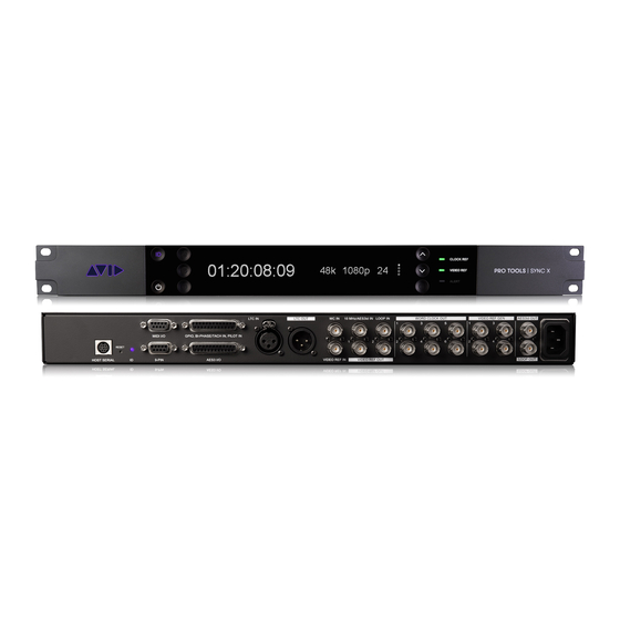
Chapter 2: Pro Tools | Sync X Front Panel Pro Tools | Sync X is controlled by Pro Tools | Ultimate software on your computer. The front panel of the unit provides displays, indicators, and controls. Pro Tools | Sync X Front Panel Features Pro Tools | Sync X front panel Power button: Press the Power button to power on the unit. -
Page 13: Settings Display
CLOCK REF LED: Indicates the status of the Clock Reference source. Mirrors the Clock Ref Status indicator in the Pro Tools Ses- sion Setup window, and also in Synchronization view in the Transport window and the Edit Window toolbar. Clock Ref LED indications Sync X Clock Ref LED Session Setup/Front Panel Clock Reference... - Page 14 Settings Display Page 3 Displays the current Video Reference Source . Video Reference Source Displays the current Video Reference Format . Format Displays the Detected Input Format of the incoming video reference signal (if any). Detected Input Format Settings Display Page 4 Displays the Positional Reference Format .
-
Page 15: Chapter 3. Pro Tools | Sync X Back Panel
Chapter 3: Pro Tools | Sync X Back Panel Pro Tools | Sync X Back Panel Connectors Pro Tools | Sync X back panel HOST SERIAL : The Host Serial port is a bidirectional (in/out) port to connect Sync X to the Serial Port on HD Native or on the primary HDX card in your system. - Page 16 WC IN : This BNC port receives Word Clock, for clock reference purposes only. Word Clock is often used with external master ™ clocks, digital consoles, and audio interfaces (such as Pro Tools | MTRX 10 MHz/AES3id IN : This BNC port receives either 10 MHz or AES3id signal depending on which is selected as the Clock Ref- erence Source in the Session Setup window.
-
Page 17: Chapter 4: Installing Pro Tools | Sync X
Chapter 4: Installing Pro Tools | Sync X Installing and setting up Pro Tools | Sync X involves the following: Unpacking Pro Tools | Sync X from the box. Registering Pro Tools | Sync X. Rack mounting Pro Tools | Sync X (optional). Connecting cables. -
Page 18: Register Pro Tools | Sync X
Register Pro Tools | Sync X Pro Tools | Sync X includes a Registration card with a redemption code and a QR code that lets you register the unit. Registering your Sync X lets you put it under Hardware Contract, access support, and access PDF documentation through your online Avid Master Ac- count. -
Page 19: Ac Power
AC Power The Pro Tools | Sync X AC connector accepts a standard AC Power Cable (included). Sync X is auto power-selecting (100V to 240V) and will automatically work with a standard modular cable to connect to AC power receptacles in any country. Host Serial Connection Serial Cable Connection to the HD Native Device or Primary HDX Card Both Pro Tools | HD Native (PCIe card or Thunderbolt) and Pro Tools | HDX support Pro Tools | Sync X. - Page 20 To connect Loop Sync between Pro Tools | Sync X and Pro Tools audio interfaces: Using a shielded BNC cable, connect the LOOP OUT port of Sync X to the Loop Sync In of your Pro Tools audio interface. Connect the LOOP IN port of Sync X to the Loop Sync Out of your Pro Tools audio interface. Making Loop Sync connections, Sync X and MTRX Studio shown When using more than one Pro Tools audio interface, make Sync X the first and last unit in the Loop Sync chain.
-
Page 21: Machinecontrol Connections
When using Sync X with Pro Tools | MTRX and other Pro Tools audio interfaces (such as HD I/O), synchronize MTRX to Sync X using Word Clock and use Loop Sync for all other Pro Tools audio interfaces. For more information on Pro Tools | MTRX, refer to the MTRX Operation Guide.pdf. MachineControl Connections Pro Tools | Sync X supports limited Serial Deck Control with Pro Tools | HDX or HD Native and MachineControl. - Page 22 Word Clock contains no positional information. If you want devices to play or record in sync, you still need to provide them with a po- sitional reference. Sync X can generate timecode to provide positional reference to other devices (see Generating and Regenerating Timecode).
-
Page 23: Launch Pro Tools
Launch Pro Tools After connecting Pro Tools | Sync X to your HDX or HD Native system, launch Pro Tools. You are notified if a firmware update is re- quired for Sync X. To launch Pro Tools and update Pro Tools | Sync X firmware: After installing Pro Tools | Sync X, launch Pro Tools | Ultimate software: •... -
Page 24: Enable Pro Tools | Sync X In Pro Tools
To update Pro Tools | Sync X firmware: Confirm that Pro Tools | Sync X is properly connected to the serial port on your primary HDX card or HD Native device. Power on your computer (or restart it if it is already running). Ensure that Pro Tools is not running. -
Page 25: Chapter 5. Configuring Pro Tools | Sync X
Chapter 5: Configuring Pro Tools | Sync X Pro Tools | Sync X is configured and controlled using Pro Tools | Ultimate software. Pro Tools | Sync X Setup in the Peripherals Dialog Enable and configure Pro Tools | Sync X in the Pro Tools Peripherals dialog ( Setup > Peripherals ). Synchronization Peripherals Setup Avid Synchronization Device The Avid Synchronization Device settings let you configure Sync X. - Page 26 Idle MTC Enabled When this option is disabled, MTC output is muted when playback is idle. When this option is enabled, MTC is continuously output from Sync X whether or not the transport is running. Enable Relay-Based GPOs When this option is enabled, GPO Output triggers 0–3 are enabled for the GPIO DB-25 port on the back panel. When disabled, there is no audible click noise from the device during playback, record, or fader start.
- Page 27 Machine Control Setup If you are using Pro Tools | MachineControl with Pro Tools | Sync X, do the following to establish basic communication. Machine Control settings in the Pro Tools Peripherals dialog To configure Machine Control: Choose Setup > Peripherals , and click the Synchronization tab. On the Synchronization page, ensure that Sync X is the current Synchronization device.
-
Page 28: Pro Tools | Sync X In The Session Setup Window
Pro Tools | Sync X in the Session Setup Window With Sync X enabled in the Synchronization page of the Peripherals dialog ( Setup > Peripherals ), you can use the Session Setup window ( Setup > Session ) to configure and control Sync X. Sync X settings configured in the Session Setup window are stored in the Sync X unit. - Page 29 Sync X Setup & External Offsets Section With Sync X selected as the Clock Master , the Sync X Setup & External Offsets section lets you configure the Clock Reference , Video Reference , and Positional Reference settings for Sync X. Clock Ref (Sample Rate Lock) Select the Clock Reference Source for Sample Rate Lock, both for Pro Tools and any connected external devices.
- Page 30 Enable VSO (variable speed override) and adjust the slider to fine-tune the speed (and pitch) of Pro Tools or any device receiving its clock reference from Sync X. VSO is available at any positional reference setting, but only when Clock Ref Source is set to Internal .
- Page 31 Detected Input Format Sync X automatically detects and displays the format of the incoming External Video Reference signal. Video Ref Status Indicator The Status light indicates whether or not the selected Video Reference Source is valid. Text appears to the right of the Status light indicating if Sync X is Generating video reference, or if it is Locked or Not Locked to the selected Video Reference Source .
-
Page 32: Transport Window And Edit Window Toolbar Synchronization View
Timecode Settings Section This section lets you configure Freewheel settings, and Audio Rate and Video Rate Pull Up and Pull Down settings. Freewheel The Freewheel section lets you configure how the Pro Tools transport behaves when it is Online and chasing timecode that is in- terrupted or corrupted. - Page 33 To show Synchronization view in the Edit Window toolbar, do one of the following: In the Edit Window menu, select Synchronization . Right-click in the Edit Window Toolbar menu and select Synchronization . Synchronization view in the Edit Window toolbar, LTC enabled Generating LTC and MTC With Pro Tools | Sync X connected and configured, Sync X generates both LTC and MTC when GEN LTC is enabled (see Gen-...
-
Page 34: Chapter 6. Using Pro Tools | Sync X
Chapter 6: Using Pro Tools | Sync X Clock References The following sections explain various clock reference configurations. Active outputs from Sync X are always synchronous with the selected clock source (internal or external). Internal Clock Pro Tools | Sync X can use its own internal clock as the Clock Reference Source . Sync X uses a double resolution JetPLL™ Clock with extremely low jitter. - Page 35 LTC (Linear Time Code) In addition to positional reference, LTC can be used as a clock reference. However, LTC cannot be read when the reference deck is stopped, or is playing back slow or at fast wind speeds (roughly 10x playback speed). Sync X will not lock until the LTC signal is within +/–...
-
Page 36: Video Reference
Video Reference Generating Video Reference The internal Video Reference generator, if enabled, locks (resolves) to the Internal Clock source. To generate video reference: Connect the VIDEO REF GEN BNC output ports on the back of Sync X to external video peripherals. In the Pro Tools Session Setup window, select Internal for the Video Reference Source . -
Page 37: Generating And Regenerating Timecode
Bi-Phase/Tach Bi-Phase/Tach (tachometer) signals are Clock Reference signals that do not contain Positional Reference information of their own. However, they do contain enough information for Sync X to simulate Positional information. In order to use the Bi-Phase/Tach sig- nal for Positional Reference, Sync X needs to know the timecode address for a particular frame of film. This positional relationship is established by parking the film device at a particular frame and setting Sync X to the equivalent timecode value using the Bi-Phase/Tach Starting Frame parameter. - Page 38 Generator Reference Rules If the Clock Reference Source is set to Internal , Internal with VSO , LTC , Pilot Tone , Bi-Phase , AES3 , AES3id , 10 MHz , or Word Clock , then the timecode generator locks to the selected clock reference. If the Clock Reference Source is set to Video Reference , the timecode generator references the signal input on the VIDEO REF IN BNC port.
-
Page 39: External Offsets And Timecode Display
To use MTC output from Sync X: Connect the Sync X MIDI Out connector to a MIDI In connector of a device that can recognize and use MTC. Typically, this would be a console, sequencer, synthesizer or sampler keyboard, a drum machine, or other device. MTC Output and Idle MTC Enabled Option MTC is normally output whenever LTC is output. -
Page 40: Example System Configurations
Example System Configurations Dolby Atmos Mixing Configuration with Sync X as Video Reference Source The following diagram shows an example of a Dolby Atmos mixing configuration using multiple Pro Tools Satellite systems, each with its own Sync X. In this case, the Recorder system Sync X provides Video Reference, Word Clock, and LTC Positional Ref- erence for the other systems. -
Page 41: Pro Tools | Sync X Routing
Pro Tools | Sync X Routing The following diagram shows signal routing for Pro Tools | Sync X with all possible sources and outputs. Chapter 6: Using Pro Tools | Sync X... -
Page 42: Appendix A. Specifications
Appendix A: Specifications General Nominal Sample Rates Sample Rate Pull Up/Down 44100 48000 88200 96000 176400 192000 45983 50050 91967 100100 183934 200200 +4.1667% and +0.1% 45938 50000 91875 100000 183750 200000 +4.1667% 45892 49950 91783 99900 183566 199800 +4.1667% and –0.1% 44144 48048... -
Page 43: Back Panel Connectors
Back Panel Connectors Connector Specifications Format: SMPTE/EBU 80-bit longitudinal, drop frame/non-drop frame Connector: 3-pin XLR female per IEC 268-12 LTC IN Speed Range: 1/10 to 30X play speed, forward or reverse Level: –24 dBu to +9 dBu, differential (pin 2 hot) Impedance: 8K ohms Format:... - Page 44 Connector Specifications Format: NTSC 525/29.97 PAL 625/50 Slow PAL/23.98 Slow PAL/24 1280 x 720/23.98 1280 x 720/24 1280 x 720/25 1280 x 720/29.97 1280 x 720/30 1280 x 720/50 1280 x 720/59.94 1280 x 720/60 VIDEO REF GEN 1920 x 1080/23.98/P 1920 x 1080/24/P 1920 x 1080/25/P 1920 x 1080/29.97/P...
- Page 45 Connector Specifications Level: 1 to 5 volts PP, 50% duty cycle AES3id IN Connector: BNC Female Termination: 75 ohms Level: 930 mV P-P (AC Coupled) AES3id OUT Connector: BNC Female Termination: 75 ohms GPIO, BI-PHASE/TACH Connector: 25-pin D-Sub female (DB25) IN, PILOT IN Frequency Range: 0 to 76.8 KHz...
-
Page 46: Clock Specifications
Connector Specifications Current Rating: 15 mA current loop Rate: 31.25 Kilobaud MIDI Time Code (MTC) Connector: 5-pin DIN female @ break out cable Cable Length: 50 feet (15 meters) max Format: RS-422A, 153.6 kbps Host Serial Connector: 8-pin mini-DIN female (proprietary pinout) Max. -
Page 47: Environmental Specifications
Environmental Specifications Operating Temperature 39.2 to 104 degrees F (4 to 40 degrees C) Storage Temperature –40 to 176 degrees F (–40 to 80 degrees C) Relative Humidity 0 to 95%, non-condensing Appendix A: Specifications 39... -
Page 48: Appendix B. Additional Synchronization Information
Appendix B: Additional Synchronization Information Video Reference Signals Video Reference Black Burst A black burst signal is essentially a “position-less” video signal. As with any “shared” video signal, you’ll want to ensure that your video feed comes from a properly buffered and distributed source, such as a video distribution amplifier, or the house video reference/black burst output of another device in the chain. -
Page 49: Bi-Phase/Tach
Word Clock allows Word Clock-compatible devices to send or receive external clock information which determines the sample rate, which in turn (where applicable) controls the play and record speed. Using just Word Clock, it is possible to create a “chain” of digital devices in your studio by picking one source as the Word Clock mas- ter, and configuring other sources to follow Word Clock. -
Page 50: Pilot Tone
However, some film equipment works in the opposite manner, which is why the Sync X Bi-Phase Tach Wiring setting in the Peripherals dialog lets you make the appropriate selection (Fwd = A leads B, or Fwd = B leads A). Calculating the direction of a Tach signal is slightly different. -
Page 51: Appendix C. Wiring Diagrams And Pin Assignments
Appendix C: Wiring Diagrams and Pin Assignments LTC IN and OUT XLR Ports The Sync X LTC In and LTC Out connectors are balanced XLRs with Pin 2 wired “+” or “hot,” Pin 3 wired “–” or “cold,” and Pin 1 wired to ground (shield). -
Page 52: Gpio, Bi-Phase/Tach In, Pilot In Db-25 Port
GPIO, BI-PHASE/TACH IN, PILOT IN DB-25 Port GPIO, Bi-Phase/Tach In, Pilot In DB-25 pin-out BI-PHASE/TACH IN Bi-Phase/Tach In... -
Page 53: Bi-Phase/Tach/Gpi/Pilot Port Interfacing Notes
GPI Input, Output (Relay), and Output (TTL) GPI Input, Output (Relay), and Output (TTL) Bi-Phase/Tach/GPI/Pilot Port Interfacing Notes The six opto-isolators are 6N137 devices. The four GPI input ports pass through 390 ohm series resistors to the cathode. The two ... -
Page 54: Aes3 I/O Db-25 Port
GPI Relay Wiring for Fader-Start Sync X provides a total of four Relay-level GPI outputs on pins 3/4, 3–10 of the DB-25 connector (see the GPI Input, Output (Relay), and Output (TTL) diagram). The GPI Relay outputs are intended to drive Relay loads only. GPI Triggers GPI output signals information: 0 (relay) = Play... -
Page 55: 9-Pin (Rs422)
9-Pin (RS422) 9-pin MIDI I/O Port MIDI I/O... -
Page 56: Host Serial Pin Assignments
Host Serial Pin Assignments The following table shows the pin assignments for the Host serial port on the back of Sync X. Sync X rear panel Mini DIN 8-pin connector pin assignments (Host) Description Direction No connection — Handshake Transmit – Ground —... -
Page 57: Appendix D. Troubleshooting
Appendix D: Troubleshooting Troubleshooting Status LEDs The status LEDs on the Sync X front panel and in the Session Setup window may help you isolate potential problems. Use the Incoming Time field in Pro Tools Session Setup Window as a Reference The Incoming Time field in the Session Setup Window indicates whether or not Sync X is receiving positional reference. -
Page 58: Factory Reset
Factory Reset If directed by Avid Customer Support, you can reset Pro Tools | Sync X to its default factory state. This process reverts the firmware and all settings. To reset Sync X to original firmware and settings: Power off the unit. Do one of the following: •... - Page 59 For Technical Support, visit www.avid.com/support...
Need help?
Do you have a question about the Pro Tools SYNC X and is the answer not in the manual?
Questions and answers