Table of Contents
Advertisement
Advertisement
Table of Contents

Related Manuals for HPE D3600


Summary of Contents for HPE D3600
- Page 1 HPE D3000 Disk Enclosure User Guide Abstract This guide describes the D3000 family of 12Gb SAS disk enclosures (D3600, D3610, D3700, D3710). Installation, cabling, configuration, and troubleshooting procedures are included. Part Number: 734753-005 Published: September 2017 Edition: 4...
- Page 2 © Copyright 2014, 2017 Hewlett Packard Enterprise Development LP The information contained herein is subject to change without notice. The only warranties for Hewlett Packard Enterprise products and services are set forth in the express warranty statements accompanying such products and services. Nothing herein should be construed as constituting an additional warranty.
-
Page 3: Table Of Contents
Unit identification (UID) button.......................16 Powering on...........................16 Cables..............................16 Cables to connect HPE D36x0/D37x0 to any HPE 6Gb SAS initiator..........16 Cables to connect HPE D36x0/D37x0 with any HPE Smart Array 12Gb SAS initiator....17 2 Technical specifications..................18 Physical specifications........................18 Power and environmental specifications....................18 Acoustic noise levels..........................18... - Page 4 Rack installation best practices.....................28 Rack Installation procedures......................28 Installing disk drives in the enclosure....................31 Disk drive options..........................31 Disk drive guidelines........................31 Installing a disk drive........................31 Installing SAS controllers or controller enclosures................33 Preparing the server...........................33 Connecting SAS cables and power cords..................34 Overview............................34 Cabling best practices........................34 Connecting SAS cables to the server or controller enclosure............35 Connecting SAS cables to cascaded disk enclosures..............36 Connecting power cords........................37...
- Page 5 Best practices for replacing hardware components................55 Verifying component failure......................55 Identifying the spare part.......................55 Replaceable parts..........................55 Replacing the failed component......................56 Replacement instructions........................56 Hardware components........................57 10 Support and other resources................59 Accessing Hewlett Packard Enterprise Support.................59 Accessing updates..........................59 Websites.............................59 Customer self repair...........................60 Remote support..........................60 Rack stability............................60 Documentation feedback........................60 11 Regulatory compliance notices................62...
- Page 6 Turkish notice..........................68 Index........................69 Contents...
-
Page 7: Hardware
The HPE 12Gb SAS disk enclosures are available in the following models: D3600/D3610: Supports up to 12 Large Form Factor (LFF) SAS drives for a maximum capacity of 7.2 TB with 600 GB SAS drives or 120 TB with 12G 10 TB SAS MDL or 6G 10 TB SATA MDL drives. -
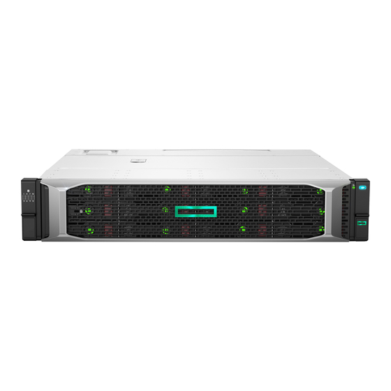
Page 8: Lff Front View
Disk drives mount in bays on the front of the enclosure. Bays are numbered sequentially from top to bottom and left to right. A drive-bay legend is included on the left bezel. Rear view NOTE: The I/O modules for both the HPE D3600/D3610 LFF and HPE D3700/D3710 SFF enclosures share the same layout. Hardware... -
Page 9: D3700/D3710 Small Form Factor Disk Enclosure Chassis
6. Rear UID button 9. Power supply D3700/D3710 Small Form Factor disk enclosure chassis Each HPE D3700/D3710 enclosure includes the following standard components: D3700/D3710 base enclosure with redundant power supplies and fan modules Two integrated 12Gb SAS I/O Modules Rack mounting hardware kit Two 0.5m HD mini-SAS cables... -
Page 10: Rear View
Rear view NOTE: The I/O modules for both the D3600/D3610 LFF and D3700/D3710 SFF enclosures share the same layout. 1. Metal cover with fan module ID 4. I/O module B 7. Rear system health LED NOTE: A pull tab is provided for label placement. -
Page 11: Disk Drives
Disk drives A variety of disk drive models are supported for use, including dual-ported and single-ported models. For more information, see the QuickSpecs for the disk enclosure, available on the D3000 website. Disk drives are hot-pluggable. Disk drive LEDs Two LEDs indicate drive status. NOTE: Both the D36x0 LFF and D37x0 SFF drive carrier system use I2C communication for drive authentication, failure and configuration info, activity animation and enhanced LEDs. -
Page 12: Front Status And Uid Module
Front status and UID module The front status and UID module includes status LEDs and a unit identification (UID) button. Front UID module LEDs Indicator Startup condition Operating condition Fault conditions 1. HDD in Bay 1 2. System Health LED Solid green Solid green Flashing amber:... -
Page 13: Unit Identification (Uid) Button
Unit identification (UID) button The unit identification (UID) button helps locate an enclosure and its components. When the UID button is activated, the UID indicators on the front and rear of the enclosure are .are illuminated. There is a UID button in the front panel, and another in the rear panel of the enclosure. NOTE: A remote session from the management utility can also illuminate the UID. -
Page 14: Fan Module
Fan module Fan modules provide cooling necessary to maintain proper operating temperature within the controller enclosure. If one fan fails, the system still runs, but Hewlett Packard Enterprise recommends replacing the module. If two fans fail (either one complete module, or one fan per module) the system shuts down. -
Page 15: I/O Module
I/O module The I/O module provides the interface between the disk enclosure and the host. Each I/O module has two ports that can transmit and receive data for bidirectional operation. I/O module LEDs LEDs on the I/O module provide status information about each I/O port and the entire module. NOTE: The following image illustrates LEDs on the I/O module. -
Page 16: Rear Power And Uid Module
Use supported SAS cables with mini-SAS connectors. A variety of SAS cables and cable lengths are supported for use with this disk enclosure. For more information, see the QuickSpecs for the disk enclosure, available on the D3000 website. Cables to connect HPE D36x0/D37x0 to any HPE 6Gb SAS initiator Name Part number HPE 0.5m External Mini SAS HD to Mini SAS... -
Page 17: Cables To Connect Hpe D36X0/D37X0 With Any Hpe Smart Array 12Gb Sas Initiator
Cables to connect HPE D36x0/D37x0 with any HPE Smart Array 12Gb SAS initiator Name Part number External 1.0m Mini-SAS HD 4x to Mini-SAS HD 4x Cable 716195-B21 External 2.0m Mini-SAS HD 4x to Mini-SAS HD 4x Cable 716197-B21 External 4.0m Mini-SAS HD 4x to Mini-SAS HD 4x Cable... -
Page 18: Technical Specifications
2 Technical specifications Physical specifications Height/Width/Depth D3600/D3610 LFF: 3.44 x 17.64 x 23.54 in (8.7 x 44.8 x 59.8 cm) D3700/D3710 SFF: 3.44 x 17.64 x 21.48 in (8.7 x 44.8 x 54.6 cm) Weight No disk drives: 38 lb (17.2 kg) D3700/D3710 SFF fully populated with SFF disk drives: 54.90 lb (24.9 kg) - Page 19 Operating Acoustic Noise (sound power) LWAd= 7.0 B Operating Acoustic Noise (sound pressure) LpAm - 53 dBA Acoustic noise levels...
-
Page 20: Deployment Types
3 Deployment types The following types of deployments are supported: Single domain In a single domain deployment, one path exists from the disk enclosure to the host. In a single domain deployment, only one I/O module in the disk enclosure is used Dual domain In a dual domain deployment, two paths exist from the disk enclosure to the host. -
Page 21: Installation
4 Installation Installation overview Installation steps include: Locating “Required items” Page 21 Completing “Preliminary tasks” Page 22 “Preparing the site” Page 27 “Racking the disk enclosure” Page 28 “Installing disk drives in the enclosure” Page 31 “Connecting SAS cables and power cords” Page 34 “Powering on the disk enclosure”... -
Page 22: Preliminary Tasks
If you are not familiar with installing and configuring storage array systems, Hewlett Packard Enterprise can install this product for you. For more information, see the Business & IT Services website: http://www.hpe.com/info/services. Different levels of assistance are available. For example, the following services might be included:... -
Page 23: Signing Up To Automatically Receive Advisories, Notices, And Other Messages
To register for and automatically receive product tips, update information, driver- and support-related advisories, see the Subscriber's Choice website: http://www.hpe.com/info/ e-updates. Click Subscribe and follow the onscreen instructions to select all of the Hewlett Packard Enterprise products for which you want to receive notices. While subscribing, indicate your delivery preference (HTML, text, or RSS) and frequency of delivery (as they become available, weekly, or monthly). -
Page 24: System And Performance Expectations
Storage planning considerations include: System and performance expectations Striping methods RAID levels Disk drive sizes and types Spare drives Array sizing (capacity) NOTE: For the minimum supported configuration, and other configuration information, see the QuickSpecs for the disk enclosure. System and performance expectations To help determine the best way to configure your storage, rank the following three storage characteristics in order of importance: Fault tolerance (high availability) -
Page 25: Disk Drive Sizes And Types
The following table compares the different RAID levels. Summary Best practices Data redundancy RAID method RAID0 RAID0 is optimized for I/O IMPORTANT: Do not use RAID0 for None Striping speed and efficient use of LUNs if fault tolerance is required. physical disk capacity, but Consider RAID0 only for noncritical provides no data redundancy. -
Page 26: Spare Disks
Spare disks Spares are disks that are not active members of any particular array, but have been configured to be used when a disk in one of the arrays fails. If a spare is present, it will immediately be used to begin rebuilding the information that was on the failed disk, using parity information from the other member disks. -
Page 27: Preparing The Site
Calculate the total weight of your equipment and verify that your site can support the weight. For HPE ProLiant server environments, consider using Rack Builder, a software tool that provides a simplified method to planning and configuring racks and rack-mountable products. -
Page 28: Racking The Disk Enclosure
Racking the disk enclosure The disk enclosure can be installed into most standard server racks. To verify that your rack is supported for use with the disk enclosure, see the QuickSpecs for the disk enclosure, available on the D3000 website. CAUTION: Install disk drives in the enclosures only after mounting the enclosures in the rack. - Page 29 To engage the front, pull the rail towards the front of the rack to engage the spring hook with the RETMA column in the same manner as the rear spring hook. NOTE: Make sure that the respective guide pins for the square or round hole rack align properly into RETMA column hole spacing.
- Page 30 The rear ends of the rails have a CTO bracket that must engage with the enclosure in order to secure it to the rails. Align the CTO bracket to the corresponding rear slot into the chassis. The movable bracket can be slid forward or back to correct position. The provided screw will secure the bracket and chassis to the rail.
-
Page 31: Installing Disk Drives In The Enclosure
Installing disk drives in the enclosure Disk drive options Depending on the enclosure model, 12 or 25 disk drives can be installed in the enclosure. A variety of disk drive models are supported for use, including dual-ported and single-ported models. For more information about supported disk drives, see the QuickSpecs for the disk enclosure, available on the D3000 website. - Page 32 IMPORTANT: When a drive is inserted in an operational enclosure, the drive LEDs flash to indicate that the drive is seated properly and receiving power. Determine the status of the hard drive. IMPORTANT: For proper airflow and cooling, a drive blank must remain installed in all unused drive bays.
-
Page 33: Installing Sas Controllers Or Controller Enclosures
D3000 website. Install all operating-system-specific service packs, patch kits, or other required tools. Install Hewlett Packard Enterprise system management and monitoring tools, such as HPE Systems Insight Manager (HPE-SIM) and the Array Configuration Utility (ACU). NOTE: For detailed installation and configuration information about the server or the software tools, see the documentation provided with the server or software. -
Page 34: Connecting Sas Cables And Power Cords
Connecting SAS cables and power cords Overview Connecting cables includes the following steps: Reading the “Cabling best practices” Page “Connecting SAS cables to the server or controller enclosure” Page “Connecting SAS cables to cascaded disk enclosures” Page “Connecting power cords” Page IMPORTANT: The following illustrations demonstrate connecting a disk enclosure to a server with an installed controller. -
Page 35: Connecting Sas Cables To The Server Or Controller Enclosure
Connecting SAS cables to the server or controller enclosure To connect the first disk enclosure to the server or controller enclosure, use a standard mini-SAS cable. IMPORTANT: When connecting this disk enclosure in a single-domain environment, only the top I/O module (I/O module A) in the disk enclosure is supported for use. Observe the following guidelines: Only use supported SAS cables with mini-SAS connectors. -
Page 36: Connecting Sas Cables To Cascaded Disk Enclosures
The number of supported cascaded disk enclosures varies per disk enclosure model and installation environment. For more information, see the QuickSpecs for the disk enclosure, controller, or controller enclosure, available on the Hewlett Packard Enterprise storage website: http://www.hpe.com/info/storage. Observe the following guidelines: Only use supported SAS cables with mini-SAS connectors. -
Page 37: Connecting Power Cords
Connecting power cords When connecting power cords, use the cords shipped with the disk enclosure. The power cord should be approved for use in your country. The power cord must be rated for the product and for the voltage and current marked on the electrical ratings label of the product. The voltage and current rating for the cord should be greater than the voltage and current rating marked on the product. -
Page 38: Powering On The Disk Enclosure
Powering on the disk enclosure After disk enclosures are physically installed and cabled, apply power to the enclosure by connecting it to a live power source. Verify that they are operating properly. Power on best practices Observe the following best practices before powering on the enclosure for the first time: Complete the server, controller, or controller enclosure installation. -
Page 39: Verifying The Operating Status Of The Disk Enclosures
Verifying the operating status of the disk enclosures To verify that the disk enclosures and disk drives are operating properly, view the enclosure and disk drive LEDs and compare them with the patterns described in the following sections. If LED patterns are not as expected, check cable connections between the devices, check the availability of your power source, review the installation procedures, and remove and reinsert the module. -
Page 40: Configuration
5 Configuration Configuration overview Regardless of the installation environment, operating system, or software tool used to configure the disk enclosure, the following tasks must be completed: Updating controller or controller enclosure firmware or drivers. Instructions are included with the controller or controller enclosure. Updating disk enclosure firmware. -
Page 41: Operation And Management
6 Operation and management Included topics: “Powering on disk enclosures” Page 41 “Powering off disk enclosures” Page 41 “Updating disk enclosure firmware” Page 41 Powering on disk enclosures IMPORTANT: Always power on disk enclosures before controller enclosures and servers. This ensures that servers, during the discovery process, identify the enclosures and installed disk drives as operational devices. - Page 42 To determine currently-installed firmware and software versions on system components, use management software utilities such as the HPE System Management Home page, Systems Insight Manager (SIM), Storage Management Utility (SMU), or Command Line Interface (CLI). To obtain the latest-available firmware and software, see the Hewlett Packard Enterprise website: http://www.hpe.com/support.
-
Page 43: Cabling Examples
7 Cabling examples The following basic cabling examples are included: “Large Form Factor D36x0 disk enclosures — maximum capacity configuration” (page 44) “Small Form Factor D37x0 disk enclosures — maximum capacity configuration” (page 45) “Dual domain example — best fault tolerance cabling” (page 46) “Dual domain —... -
Page 44: Large Form Factor D36X0 Disk Enclosures - Maximum Capacity Configuration
Large Form Factor D36x0 disk enclosures — maximum capacity configuration This example illustrates cabling for a single-domain configuration. In this configuration, note the following: P1 on the disk enclosure I/O module is treated as the SAS “in” port. P2 on the disk enclosure I/O module is treated as the SAS “out” port. In single-domain configurations, one cable path is created between the host, the primary disk enclosure, and additional cascaded disk enclosures. -
Page 45: Small Form Factor D37X0 Disk Enclosures - Maximum Capacity Configuration
Small Form Factor D37x0 disk enclosures — maximum capacity configuration This example illustrates cabling for a single-domain configuration. In this configuration, note the following: P1 on the disk enclosure I/O module is treated as the SAS “in” port. P2 on the disk enclosure I/O module is treated as the SAS “out” port. In single-domain configurations, one cable path is created between the host, the primary disk enclosure, and additional cascaded disk enclosures. -
Page 46: Dual Domain Example - Best Fault Tolerance Cabling
Dual domain example — best fault tolerance cabling This example illustrates cabling for a dual-domain configuration in a pattern that offers best possible fault tolerance. In this configuration, note the following: A multi-port, dual-domain controller in the host and dual-port disk drives in the disk enclosure are required for dual-domain deployments. -
Page 47: Dual Domain - Best Performance Cabling
Dual domain — best performance cabling This example illustrates cabling for a dual-domain configuration in a pattern that offers best possible performance. In this configuration, note the following: A multi-port, dual-domain controller in the host and dual-port disk drives in the disk enclosure are required for dual-domain deployments. -
Page 48: Dual Domain-Alternative Cabling
Dual domain—alternative cabling This example illustrates cabling for a dual-domain configuration in a pattern that offers a balance of fault tolerance and performance. In this configuration, note the following: A multi-port, dual-domain controller in the host and dual-port disk drives in the disk enclosure are required for dual-domain deployments. -
Page 49: Troubleshooting
8 Troubleshooting If the enclosure does not initialize IMPORTANT: After a power failure, the system automatically returns to the On state when A/C power is restored, except in the following cases: If both power supplies are damaged. If there is a single power supply in the system, and it is damaged. Ensure that power has been applied to the enclosure. -
Page 50: Is The Enclosure Rear Fault Led Amber
Is the enclosure rear fault LED amber? Answers Possible Reasons Actions Functioning properly. No action required Rear power and UID module might Be sure that the rear power and UID not be inserted properly, might have module is undamaged and is fully a damaged connector, or might have seated. -
Page 51: Is The Fan Led Amber
Is the fan LED amber? Answers Possible Reasons Actions Functioning properly. No action required Fan might not be inserted properly, Be sure that the fan is undamaged might have a damaged connector, or and is fully seated. might have failed. Contact an authorized service provider for assistance. -
Page 52: Recognizing Disk Drive Failure
Management CD.) ADU lists all failed drives. Operating System log files For additional information about diagnosing disk drive problems, see the HPE ProLiant Servers Troubleshooting Guide. Effects of a disk drive failure When a disk drive fails, all logical drives that are in the same array are affected. Each logical drive in an array might be using a different fault-tolerance method, so each logical drive can be affected differently. -
Page 53: Automatic Data Recovery (Rebuild)
To minimize the likelihood of fatal system errors, take these precautions when removing failed drives: Do not remove a degraded drive if any other drive in the array is offline (the online LED is off). In this situation, no other drive in the array can be removed without data loss. Exceptions: ◦... -
Page 54: Failure Of Another Drive During Rebuild
System performance is affected during the rebuild, and the system is unprotected against further drive failure until the rebuild has finished. Therefore, replace drives during periods of low activity when possible. CAUTION: If the Online LED of the replacement drive stops blinking and the amber fault LED glows, or if other drive LEDs in the array go out, the replacement drive has failed and is producing unrecoverable disk errors. -
Page 55: Replacement Procedures
9 Replacement procedures Customer self repair (CSR) Information in (page 57) identifies hardware components that are customer replaceable. Using WEBES, ISEE or other diagnostic tools, a support specialist will work with you to diagnose and assess whether a replacement component is required to address a system problem. The specialist will also help you determine whether you can perform the replacement. -
Page 56: Replacing The Failed Component
Placing removed cables on the floor or other surfaces, where they might be walked on or otherwise compressed. Replacement instructions Printed instructions are shipped with the replacement part. Instructions for all replaceable components are also posted to the Hewlett Packard Enterprise website: http://www.hpe.com/ support/manuals. Replacement procedures... -
Page 57: Hardware Components
Hardware components Hardware components... - Page 58 9. I/O module Mandatory 10. Fan module Mandatory 11. Front Unit ID Mandatory 12. Disk drive Mandatory To order a replacement part, contact a Hewlett Packard Enterprise-authorized service provider or see the Hewlett Packard Enterprise Parts Store online: http://www.hpe.com/buy/parts Replacement procedures...
-
Page 59: 10 Support And Other Resources
10 Support and other resources Accessing Hewlett Packard Enterprise Support For live assistance, go to the Contact Hewlett Packard Enterprise Worldwide website: www.hpe.com/assistance To access documentation and support services, go to the Hewlett Packard Enterprise Support Center website: www.hpe.com/support/hpesc Information to collect... -
Page 60: Customer Self Repair
Hewlett Packard Enterprise is committed to providing documentation that meets your needs. To help us improve the documentation, send any errors, suggestions, or comments to Documentation Feedback (docsfeedback@hpe.com). When submitting your feedback, include the document title, part number, edition, and publication date located on the front cover of the document. For... - Page 61 online help content, include the product name, product version, help edition, and publication date located on the legal notices page. Documentation feedback...
-
Page 62: 11 Regulatory Compliance Notices
11 Regulatory compliance notices This section contains regulatory notices for the HPE StorageWorks D3600/3700 12Gb SAS disk enclosures. Regulatory compliance identification numbers For the purpose of regulatory compliance certifications and identification, this product has been assigned a unique regulatory model number. The regulatory model number can be found on the product nameplate label, along with all required approval markings and information. -
Page 63: Canadian Notice (Avis Canadien)
(European Norms) which are listed on the EU Declaration of Conformity issued by Hewlett Packard Enterprise for this product or product family. This compliance is indicated by the following conformity marking placed on the product: Certificates can be obtained from http://www.hpe.com/info/certificates. Hewlett Packard Enterprise GmbH, HQ-TRE, Herrenberger Strasse 140, 71034 Boeblingen, German... -
Page 64: Taiwanese Notices
Taiwanese notices BSMI Class A notice Chinese notice Recycling notices English notice Bulgarian notice Czech notice Regulatory compliance notices... -
Page 65: Danish Notice
Danish notice Dutch notice Estonian notice Finnish notice French notice Recycling notices... -
Page 66: German Notice
German notice Greek notice Hungarian notice Italian notice Latvian notice Regulatory compliance notices... -
Page 67: Lithuanian Notice
Lithuanian notice Polish notice Portuguese notice Romanian notice Slovak notice Recycling notices... -
Page 68: Spanish Notice
Spanish notice Swedish notice Turkish notice Türkiye Cumhuriyeti: EEE Yönetmeliğine Uygundur Regulatory compliance notices... - Page 69 Index if the fan LED is amber, 51 if the I/O module fault LED is amber, 50 accessing if the power on/standby LED is amber, 50 updates, 59 if the power supply LED is amber, 50 recognizing disk drive failure, 52 diagnostic tools, 40 best practices disk drives...
- Page 70 help defined, 13 obtaining, 22 LEDs, 13 Hewlett Packard Enterprise powering off, 41 Subscriber's Choice for Business, 23 powering on best practices, 38 troubleshooting, 49 I/O module preparing the controller defined, 15 for disk enclosure, 33 LEDs, 15 preparing the server installation for disk enclosure, 33 assistance, Hewlett Packard Enterprise, 22...
- Page 71 Taiwanese notices, 64 troubleshooting powering on, 49 UID button front, 13 rear, 16 updates accessing, 59 utilities, supported, 40 ventilation requirements, 27 warnings personal injury, equipment damage, 28 power related, 37 rack stability, 60 websites, 59 customer self repair, 60 weight considerations, 27...
Need help?
Do you have a question about the D3600 and is the answer not in the manual?
Questions and answers